The Wimshurst Electrostatic Machine
 Years ago (1973-1975) I built a first
series of electrostatic machines. With this I learned a lot about
electricity, and I still think that all people interested in
electricity or electronics shall try these machines to get a real
feel of the subject. At least, high voltage static electricity is
something that you can see and feel.
Years ago (1973-1975) I built a first
series of electrostatic machines. With this I learned a lot about
electricity, and I still think that all people interested in
electricity or electronics shall try these machines to get a real
feel of the subject. At least, high voltage static electricity is
something that you can see and feel.
The best machine I could build at that time was a Wimshurst
machine. I learned about it in old physics books [1], and it was not difficult to build one
that was immediately successful. Following are instructions on
how to build a machine similar to mine. Take also a look at the
several pictures and plans of Wimshurst machines in other areas
of the site, some much better
than this one.
The Wimshurst machine was invented by James Wimshurst, in
England, and first described in 1883. Similar structures,
although sectorless, were previously studied, in Germany, by Holtz and Poggendorff, by 1869 [p45][p47], and
Musaeus, by 1871 [p47][27][p93]. A sectored machine of rather poor
performance was described by Holtz in 1876 [29][p94]. This machine eventually become the
most popular electrostatic machine, due to its relatively
reliable operation and simple construction.
To build one what you need is: Two plastic disks, with about 31 cm of
diameter (It is possible to use exactly two old LP disks, but the
result is rather ugly). I used two acrylic disks, about 2 mm
thick, with 20 cm of diameter This is rather small, but big
enough to allow the observation of all the important
electrostatic phenomena, without taking too much space. If you
want some power, make disks with more than 30 cm. The spark
length that can be obtained is about 1/3 of the diameter of the
disks.
Mount in the middle of the disks wood cylinders, to be used as
"bosses" to turn the disks, with precise holes to pass
a steel axle in the center. Make grooves around the cylinders to
be used as pulleys where the cords that will move the disks will
pass. I actually used more elaborated bosses, turned in a lathe,
with flat faces to be glued to the disks in one side and small
pulleys at the other side. Metal or a plastic as nylon can also
be used for the bosses. Mount the assembly in a wood support
composed of a base and two upright supports, in a way that allows
the disks to rotate in opposite directions, maintaining a
separation of 1-2 mm, never touching. The distance can be
proportionally larger with larger disks. The construction must be
solid and well balanced. I fixed the bosses to the disks with
glue, adjusting the disk positions while the glue was drying.
Larger machines require screws to fix the disks to the bosses. I
like to use three flat-head screws with a flexible washer between
the disks and the bosses, so the pressure of the screws can be
adjusted to make the disks run true. Ball bearings between the
bosses and the axle are a good idea. I used some cardboard
washers soaked with paraffin to adjust the spacing between the
disks. It's important to select the plates for the disks with
very uniform thickness, or they will vibrate when turning fast.
If this happens, it's possible to glue small lead blocks to the
edges of the disks, at the lighter sides. Not a perfect solution,
but works.
Mount in the same support two pulleys, larger than the boss
pulleys, in an axle moved by a crank. This axle can pass a few cm
below the disks, mounted on adequate bearings. For this small
machine, I just made holes in the upright supports and inserted a
layer of brass foil between the axle and the wood. In other
machines I used brass, bronze, or Nylon for the bearings. Ball
bearings are the best solution. Pass cords from these pulleys to
the boss pulleys. Turning the crank shall make the disks turn in
opposite directions at several turns per second. Cross one of the
cords to make one of the disks turn in the opposite direction. I
used rubber cords of the type used in tape recorders to connect
the pulleys to the disks. Large "O" rings make good
cords too, but that don't last much. Round leather cords are the
classical material, but sewing machine cords are too thick for a
machine of this size. An exellent material are polyurethane cords
that can be joined by melting. When joining the cord that will be
crossed, make two loops on it. In this way the cord ends with a
half twist, and operates better. For the other cord, make just
one loop.
Make a set of aluminum sectors from thin aluminum foil. The
sectors shall be perfectly flat stripes a few centimeters long, with one side
larger that the other, and with rounded corners. A minimum width
of about 1 cm is adequate. These sectors are to be glued to the
plastic disks, at the external face. forming a symmetrical
pattern around each disk. The number of sectors shall be even, so
there are always two exactly opposite. More sectors is better
than few, with the usual number being between 16 and 40 (I used
18). The output current of the machine is proportional to the
area covered by the sectors. The maximum spark length that the
machine can generate can be estimated as the sum of sector
spacings along a third (for the neutralizers at 60 degrees) of a
disk. A distance between sectors similar to their average width
is adequate (they have the outer side larger than the inner side
to keep this fixed distance along their length). Wider sectors
result in more current, but in smaller sparks. The distance from
the sectors to the disk bosses also limits the maximum voltage.
Originally, I used kitchen aluminum foil for the sectors. To glue
the sectors to the disks, I used common paper glue, soluble in
alcohol, fixing tightly the strips to the disks, with help of a
piece of cardboard, leaving no bubbles. The excess of glue I
removed carefully after it dried with alcohol, leaving the disks
perfectly clean. It is important to do not leave any sharp corner
in these sectors. The thicker foil used in discardable food
containers (a pizza pan is ideal) is a good material for sectors,
and is more resistant to wear. In this case a stronger glue is
required. A "contact" glue based in synthetic rubber is
adequate, and results in a clean disk that can be used almost
immediately. A very convenient possibility is to make sectors
using adhesive aluminum tape, of the type sold as "metal
repair tape". Look for a type that has a backing foil, that
simplifies the operation of marking and cutting out the sectors.
To make the sectors, make first a hard cardboard template, a bit
smaller than the desired sectors, use it to mark the metal,
running a pencil around it (hence the smaller size). Cut the
sectors carefully with scissors. To apply the sectors with
precision, it's enough to make pencil marks on the disks, or to
draw a template that is kept under transparent disks.
Adapt to the upright supports two solid wires having at the
extremes very thin flexible metallic brushes (I used just one
thin wire as brush) that touch the disk sectors at opposite sides
of each disk, at adjustable 45-60 degrees angles with the
horizontal and at crossed positions. These "neutralizer
bars" shall short-circuit two opposite sectors when they
pass under their brushes. Thin silver foil strips is the ideal
material for the brushes. The thin nickel-chrome wire from a
high-value wire-wound resistor can also be used, thin enough to
not scratch the disks or the sectors. The brushes can be fixed to
the neutralizer bars with a section of plastic wire insulation,
can be inserted in holes at the ends of the bars, or some other
form that allows simple replacement of broken brush wires. The
neutralizer bars are fixed to metallic rings, fixed to the
upright supports of the machine by screws through their centers
at the outer sides of the upright supports, or better, directly
in the same axle of the disks, at the inner sides of the
supports. As the centers of the neutralizer bars are neutral, it
is not important if they are electrically connected to the
structure of the machine or insulated from it.
The basic Wimshurst machine is now ready. In a dry day, with
the disks very clean, turning the crank shall rapidly charge the
disks to a very high voltage, what you can easily recognize by
the noise of small sparks between the sectors, the ozone smell,
the electric field pulling the hair of your hands, and the effort
you must apply to the crank to keep the disks turning. In humid
weather, a hair dryer can be used to dry the machine and make it
work. Some carnauba wax in the disks helps to make them highly
insulating and nonhygroscopic.
To complete the machine, build the charge collectors. The
disks become charged at opposite polarities at two quadrants, and
at identical polarities at the two others. Adjust the position of
the neutralizing bars to position the quadrants where both disks
have identical polarities at the two sides of the machine. In the
correct position, the disks pass first under a charge collector,
and then under the closest neutralizer brush (easy to verify, as
nothing will be collected if you arrange the neutralizing bars in
the wrong position). The collectors can be two thick solid wires
with U forms with sharp points directed at the disk sectors (not
touching them, of course) fixed to them. The charge collectors
are connected to a spark gap that is the machine output, and the
assemblies are mounted in long insulator supports. The insulation
of the charge collector and terminal assemblies is of fundamental
importance. The insulators must be as long as possible and made
of material with extremely high electrical resistivity, as
acrylic plastic. Wood or similar materials act as total short
circuits, and are not suitable for this purpose. The assemblies
must also be kept away from any other part of the machine
structure. I mounted the collectors and spark gap in a acrylic
bar fixed to the machine support, with some screws to allow
adjustments in the position of the collectors. Be careful to do
not allow the collectors to touch the disks. This is the most
common problem with these machines, and may cause extensive
damage to the disks. It's recommended to make the collector points
with flexible thin wire, so they can't scratch the disks.
Do not leave any
sharp point or corner in the assembly, with the exception of the
charge collector points, or charge will be lost to the air. I
made the spark gap and collector assembly with brass wires 3 mm
thick, connected through aluminum balls.
Screws cut at the end of bars with loops at the other end fix the spark
gap bars at the chosen angle. The spark gap was made
with two aluminum balls with 1 cm diameter, turned in a lathe.
The diameter of the terminal balls shall be consistent with the
size of the machine. Too small spheres result in weak short
sparks and just corona if the terminals are separated beyond a
certain distance. Too large spheres result in short, strong
sparks and nothing if the balls are too separated, due to
insufficient voltage. A good rule is that the diameter of the
terminal spheres shall be of about 1/15 of the diameter of the
disks.
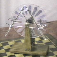
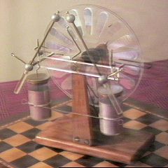
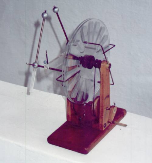
Front view of the machine. Back view.
 The spark gaps produce a practically
continuous faint spark, a few cm long in my machine, while the
disks are turning. To get stronger sparks, I added two Leyden jar
capacitors, one to each side of the spark gap. I made them using
cylindric plastic boxes, with aluminum foil strips glued inside
and outside, with a margin of a few cm to the opening of the box
for insulation. To the outer side of each box I fixed a wire with
a terminal, and passed another through the lid, making contact
with steel wool inside the box, that makes contact with the inner
foil. This wire is terminated in a closed loop, or a ball (no
points), and has a form of a hook that can be used to hang the
capacitor in the spark gap structure. One capacitor is used at
each machine terminal, with the outer plates interconnected by
a wire. This assembly results in intense sparks at each few turns
of the disks. Note that the capacitors are in series, and a
pulsed output is available over a load placed between them, at
each spark. It is also possible to use just one Leyden jar, or to
put them in parallel, what doubles or quadruples the energy ot
each spark. But the voltage attained can be not so high because
the losses are higher due to the smaller insulation. An
improvement was to add small steel balls glued to the spark gap
balls, separated by small plastic tube insulators. They generate
more intense electric fields, and little sparks between the small
balls and the main terminals trigger long sparks across the
terminals. This works better with the positive terminal
inclinated in the direction of the negative terminal. The maximum
spark length increased from 2 cm to 5 cm.
The spark gaps produce a practically
continuous faint spark, a few cm long in my machine, while the
disks are turning. To get stronger sparks, I added two Leyden jar
capacitors, one to each side of the spark gap. I made them using
cylindric plastic boxes, with aluminum foil strips glued inside
and outside, with a margin of a few cm to the opening of the box
for insulation. To the outer side of each box I fixed a wire with
a terminal, and passed another through the lid, making contact
with steel wool inside the box, that makes contact with the inner
foil. This wire is terminated in a closed loop, or a ball (no
points), and has a form of a hook that can be used to hang the
capacitor in the spark gap structure. One capacitor is used at
each machine terminal, with the outer plates interconnected by
a wire. This assembly results in intense sparks at each few turns
of the disks. Note that the capacitors are in series, and a
pulsed output is available over a load placed between them, at
each spark. It is also possible to use just one Leyden jar, or to
put them in parallel, what doubles or quadruples the energy ot
each spark. But the voltage attained can be not so high because
the losses are higher due to the smaller insulation. An
improvement was to add small steel balls glued to the spark gap
balls, separated by small plastic tube insulators. They generate
more intense electric fields, and little sparks between the small
balls and the main terminals trigger long sparks across the
terminals. This works better with the positive terminal
inclinated in the direction of the negative terminal. The maximum
spark length increased from 2 cm to 5 cm.
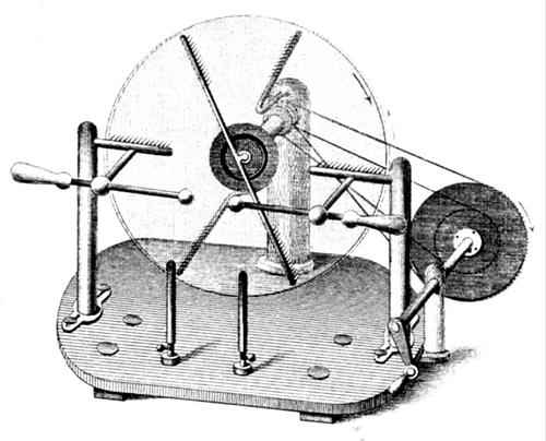
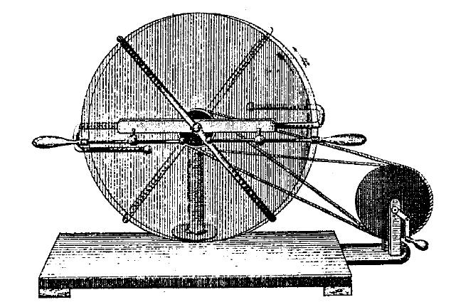
How the Wimshurst machine works.
The WMD program, that can
predict spark length and output current based on the dimensions
of the disks of a Wimshurst machine, and calculate the correct
shape for the sectors.
Created: 1996
Last update: 14 June 2011.
Created and maintained by Antonio Carlos M.
de Queiroz
Return to Electrostatic Machines