| xPC Target | |
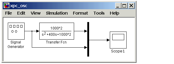
Creating a Simple Simulink Model
This tutorial uses a simple Simulink model to explain the tasks you need to do with xPC Target. If you are an experienced Simulink user, you can skip creating this model.
The model includes a transfer function and a signal generator block. If you want to visualize signals while simulating your model, you need to add a standard Simulink Scope block:
xpc_osc and then click OK.
Since xPC Target does not support data uploading with external mode, you cannot use the Simulink Scope block to visualize signals from an xPC Target application running in real time. Instead, use an xPC Target Scope block. See Adding an xPC Target Scope Block.
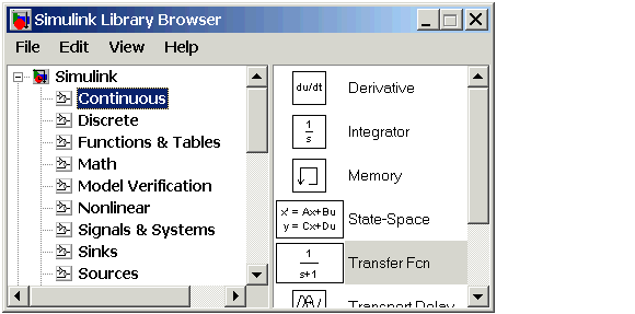
For information on creating a Simulink model and adding signal and scope blocks, see the Using Simulink documentation.
| | Simulink Model | Adding a Simulink Outport Block | |