| Real-Time Windows Target | |
Variations with Channel Selection
For a better understanding of how to specify device settings when using both analog and digital signals, this section uses the I/O board DAS-1601 from Keithley-Metrabyte as an example. The following is a specification summary of the DAS-1601 board:
This section explores different configurations for input signals.
Once an Analog Input block has been placed in the model and the I/O board selected and configured, you can set up the Analog Input block to handle input signals.
Single analog input -- The most basic case is for a single analog input signal that will be physically connected to the first analog input channel on the board. In the Block Parameter: Analog Input dialog box, and the Input channels box, enter
The use of brackets is optional for a single input.
Input vector with differential analog -- Analog channels are numbered starting with channel 1 and continue until you reach a number corresponding to the maximum number of analog signals supported by the I/O board.
In the case of the DAS-1601, when configured as differential inputs, eight analog channels are supported. The analog input lines are numbered 1 through 8. The complete input vector is
If you wanted to use the first four differential analog channels, enter
Input vector with single-ended analog -- Now, assume your DAS-1601 board is configured to be single-ended analog input. In this case, 16 analog input channels are supported. The complete input vector is
To use the first four single-ended analog input channels, enter
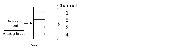
This illustration shows the resulting block diagram.
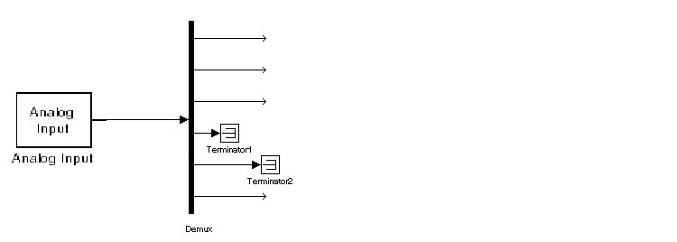
We do not recommend specifying more channels than you actually use in your block diagram. This results in additional overhead for the processor with A/D or D/A conversions. In this case, for example, even though some channels are not actually used in the block diagram, these channels are still converted.
You could attach terminator blocks to channels 4 and 5 inside your block diagram after passing the Analog Input block vector into a Demux block. Adding terminator blocks provides you with graphical information in your block diagram to clearly indicate which channels you connected or are available. The penalty is that even the terminated channels are converted, adding some computational overhead.
This illustration shows the block implementation.
Depending on the board and the number of channels used, I/O conversion time can affect the maximum sample rate that can be achieved on your system. Rather than converting unused channels, we recommend specifying only the set of channels that are actually needed for your model.
| | Output Signals from an I/O Block | Using Analog I/O Drivers | |