| Real-Time Windows Target |
  |
Output Signals from an I/O Block
I/O driver blocks output multiple signals as a vector instead of individual channels or lines. To connect the individual channels and lines to parts of your Simulink model, you need to separate the vector with a Demux block.
After you add and configure an I/O driver block in your Simulink model, you can separate and connect the output signals from the blocks:
In the Simulink window, and from the View menu, click Show Library Browser.
- The Simulink Library Browser opens.
- Double-click Signal Routing. From the list in the right column, click-and-drag Demux to your Simulink model.
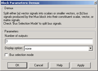
- Double-click the Demux block. The Block Parameters: Demux dialog box opens. Enter the number of lines leaving the Demux block. For example, if you entered three channels in the Analog Input driver block, enter
3 in the Number of outputs box.

- Click OK.
- Finish making connections and selecting display options.
- Connect the Analog Input block to the Demux block input.
- Connect each of the Demux block output lines to the input of other blocks.
- In the Simulink window, and from the Format menu, click Wide Nonscalar Lines, and click Signal Dimensions.
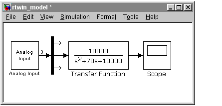
- Your model will look similar to the figure shown below. In this simple example, inputs 1 and 2 are not connected, but they could be connected to other Simulink blocks.

 | Encoder Input Block | | Variations with Channel Selection |  |


