
| Real-Time Workshop |   |
Other Interactions Between Simulink
and Real-Time Workshop
The Simulink engine propagates data from one block to the next along signal lines. The data propagated are
The first stage of code generation is compilation of the block diagram. This compile stage is analogous to that of a C program. The C compiler carries out type checking and preprocessing. Similarly, Simulink verifies that input/output data types of block ports are consistent, line widths between blocks are of the correct thickness, and the sample times of connecting blocks are consistent.
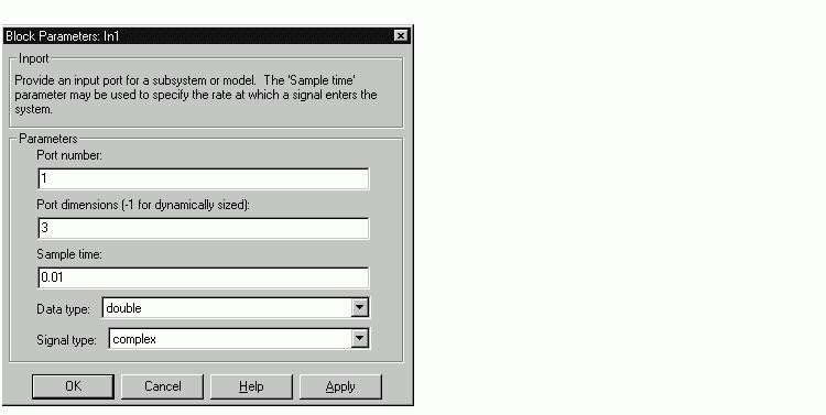
The Simulink engine typically derives signal attributes from a source block. For example, the Inport block's parameters dialog box specifies the signal attributes for the block.

In this example, the Inport block has a port width of 3, a sample time of .01 seconds, the data type is double, and the signal is complex.
This figure shows the propagation of the signal attributes associated with the Inport block through a simple block diagram.

In this example, the Gain and Outport blocks inherit the attributes specified for the Inport block.
Sample Time Propagation
Inherited sample times in source blocks (e.g., a root inport) can sometimes lead to unexpected and unintended sample time assignments. Since a block may specify an inherited sample time, information available at the outset is often insufficient to compile a block diagram completely. In such cases, the Simulink engine propagates the known or assigned sample times to those blocks that have inherited sample times but which have not yet been assigned a sample time. Thus, Simulink continues to fill in the blanks (the unknown sample times) until sample times have been assigned to as many blocks as possible. Blocks that still do not have a sample time are assigned a default sample time according to the following rules:
To ensure a completely deterministic model (one where no sample times are set using the above rules), you should explicitly specify the sample time of all your source blocks. Source blocks include root inport blocks and any blocks without input ports. You do not have to set subsystem input port sample times. You may want to do so, however, when creating modular systems.
An unconnected input implicitly sources ground. For ground blocks and ground connections, the default sample time is derived from destination blocks or the default rule.

All blocks have an inherited sample time (Ts = -1). They will all be assigned a sample time of (Tf - Ti)/50.
Block Execution Order
Once Simulink compiles the block diagram, it creates a model.rtw file (analogous to an object file generated from a C file). The model.rtw file contains all the connection information of the model, as well as the necessary signal attributes. Thus, the timing engine in Real-Time Workshop can determine when blocks with different rates should be executed.
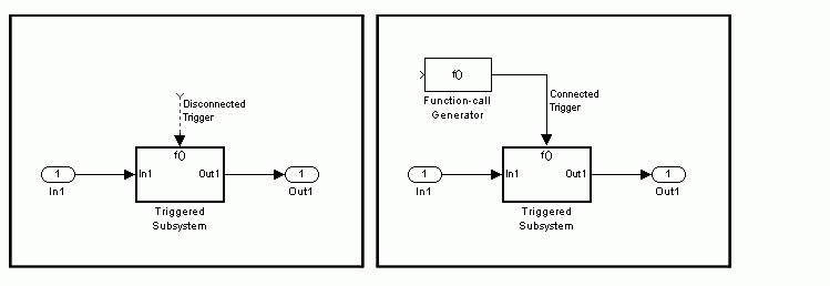
You cannot override this execution order by directly calling a block (in hand-written code) in a model. For example, the disconnected_trigger model below will have its trigger port source to ground, which may lead to all blocks inheriting a constant sample time. Calling the trigger function, f(), directly from user code will not work correctly and should never be done. Instead, you should use a function-call generator to properly specify the rate at which f() should be executed, as shown in the connected_trigger model below.

Instead of the function-call generator, you could use any other block that can drive the trigger port. Then, you should call the model's main entry point to execute the trigger function.
For multirate models, a common use of Real-Time Workshop is to build individual models separately and then hand-code the I/O between the models. This approach places the burden of data consistency between models on the developer of the models. Another approach is to let Simulink and Real-Time Workshop ensure data consistency between rates and generate multirate code for use in a multitasking environment. The Real-Time Workshop interrupt template and VxWorks support libraries provide blocks that support both synchronous and asynchronous I/O via a double-buffering scheme. For a description of the Real-Time Workshop libraries, see Asynchronous Support For more information on multirate code generation, see Models with Multiple Sample Rates
Algebraic Loops Unsupported
Real-Time Workshop does not support models containing algebraic loops. An algebraic loop exists whenever the output of a block having direct feedthrough (such as Gain, Sum, Product, and Transfer fcn) is fed back as an input to the same block. Simulink is often able to solve models that contain algebraic loops, such as the diagram shown below.
The code generator does not produce code that solves algebraic loops. This restriction includes models that use Algebraic Constraint blocks in feedback paths.
 | Tracing Generated Code Back to Your Simulink Model | Selecting a Target Configuration |  |