| Real-Time Workshop | |
How MathWorks Tools Streamline Development
Figure D-3 is a high-level view of a traditional development process without the MathWorks tools.
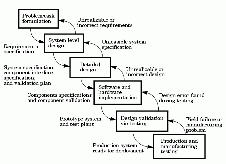
Figure D-3: Traditional Development Process Without MathWorks Tools
In Figure D-3, each block represents a work phase. Documents are used to coordinate the different work phases. In this environment, it is easy to go back one work phase, but hard to go back multiple work phases. In this environment, design engineers (such as control system engineers or signal processing engineers) are not usually involved in the prototyping phase until many months after they have specified the design. This can result in poor time to market and inferior quality.
In this environment, different tools are used in each phase. Designs are communicated via paper. This enforces a serial, rather than an iterative, development process. Developers must reenter the result of the previous phase before they can begin work on a new phase. This leads to miscommunication and errors, resulting in lost work hours. Errors found in later phases are very expensive and time consuming to correct. Correction often involves going back several phases. This is difficult because of the poor communication between the phases.
The MathWorks does not suggest or impose a development process. The MathWorks tools can be used to complement any development process. In the above process, use of our tools in each phase can help eliminate paper work.
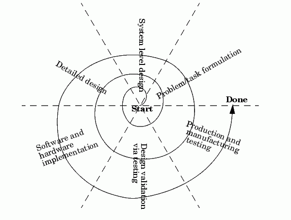
Our tools also lends itself well to the spiral design process shown in Figure D-4.
Figure D-4: Spiral Design Process
Using the MathWorks tools, your model represents your understanding of your system. This understanding is passed from phase to phase in the model, reducing the need to go back to a previous phase. In the event that rework is necessary in a previous phase, it is easier to transition back one or more phases, because the same model and tools are used in all phases.
A spiral design process iterates quickly between phases, enabling engineers to work on innovative features. The only way to do this cost effectively is to use tools that make it easy to move from one phase to another. For example, in a matter of minutes a control system engineer or a signal processing engineer can validate an algorithm on a real-world rapid prototyping system. The spiral process lends itself naturally to parallelism in the overall development process. You can provide early working models to validation and production groups, involving them in your system development process from the start. This helps compress the overall development cycle while increasing quality.
Another advantage of the MathWorks tools is that it enables people to work on tasks that they are good at and enjoy doing. For example, control system engineers specialize in design control rules, while embedded system engineers enjoy assembling systems consisting of hardware and low-level software. It is possible to have very talented people perform different roles, but it is not efficient. Embedded system engineers, for example, are rewarded by specifying and building the hardware and creating low-level software such as device drivers, or real-time operating systems. They do not find data entry operations, such as the manual conversion of a set of equations to efficient code, to be rewarding. This is where the MathWorks tools shines. The equations are represented as models and Real-Time Workshop converts them to highly efficient code ready for deployment.
Role of the MathWorks Tools in Your Development Process
The following figure outlines where the MathWorks tools, including Real-Time Workshop, helps you in your development process.
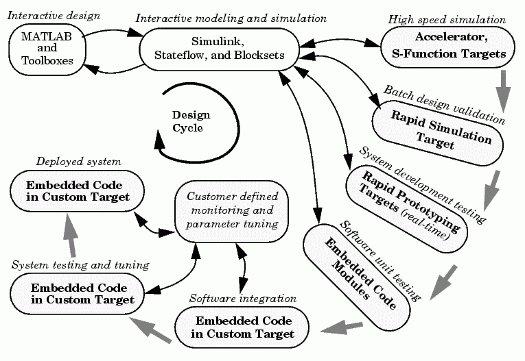
Figure D-5: Roles of MathWorks Tools in Software Design
Early in the design phase, you will start with MATLAB and Simulink to help you formulate your problems and create your initial design. Real-Time Workshop helps with this process by enabling high-speed simulations via Simulink Accelerator (also part of Simulink Performance Tools), and the S-function Target for componentization and model speed-up.
After you have a functional model, you may need to tune your model's coefficients. This can be done quickly using Real-Time Workshop Rapid Simulation Target for Monte-Carlo type simulations (varying coefficients over many simulations).
After you've tuned your model, you can move into system development testing by exercising your model on a rapid prototyping system such as the Real-Time Windows Target or the xPC Target. With a rapid prototyping target, you connect your model to your physical system. This lets you locate design flaws or modeling errors quickly.
After your prototype system is created, you can use the Real-Time Workshop Embedded Coder to create embeddable code for deployment on your custom target. The signal monitoring and parameter tuning capabilities enable you to easily integrate the embedded code into a production environment equipped with debugging and upgrade capabilities.
| | Integration with Simulink | Code Formats | |