| SimPowerSystems |
  |
PWM Generator
Generate pulses for a carrier-based pulse width modulator (PWM)
Library
Extras/Control Blocks
Description
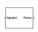
The PWM Generator block generates pulses for carrier-based pulse width modulation (PWM) systems. The block can be used to fire the self-commuted devices (FETs, GTOs, or IGBTs) of single-phase, two-phase, three-phase, or a combination of two three-phase bridges.
The number of pulses generated by the PWM Generator block is determined by the number of bridge arms you have to control:
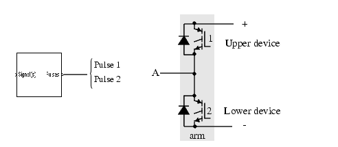
- Two pulses are generated for a one-arm bridge. Pulse 1 fires the upper device and pulse 2 fires the lower device (shown for the IGBT device).
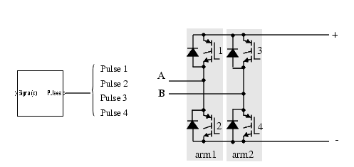
- Four pulses are generated for a two-arm bridge. Pulses 1 and 3 fire the upper devices of the first and second arm. Pulses 2 and 4 fire the lower devices.
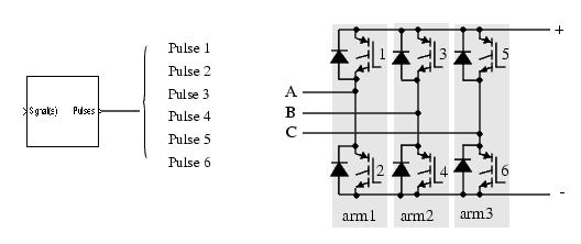
- Six pulses are generated for a three-arm bridge. Pulses 1, 3, and 5 fire the upper devices of the first, second, and third arms. Pulses 2, 4, and 6 fire the lower devices.
- Twelve pulses are generated for a double three-arm bridge. The first six pulses (1 to 6) fire the six devices of the first three-arm bridge and the last six pulses (7 to 12) fire the six devices of the second three-arm bridge.
The pulses are generated by comparing a triangular carrier waveform to a reference sinusoidal signal. The reference signal can be generated by the PWM generator itself, or it can be generated from a signal connected at the input of the block. In the second option, the PWM Generator needs one reference signal to generate the pulses for a single- or a two-arm bridge, or it needs a three-phase reference signal to generate the pulses for a three-phase bridge (single or double bridge).
The amplitude (modulation), phase, and frequency of the reference signals are set to control the output voltage (on the AC terminals) of the bridge connected to the PWM Generator block.
The pulses that fire the two devices of an arm bridge are complementary one to the other; for example, the pulse 4 is low (0) when the pulse 3 is high (1). This is illustrated in the next two figures.
The following figure displays the two pulses generated by the PWM Generator block when programmed to control a one-arm bridge.
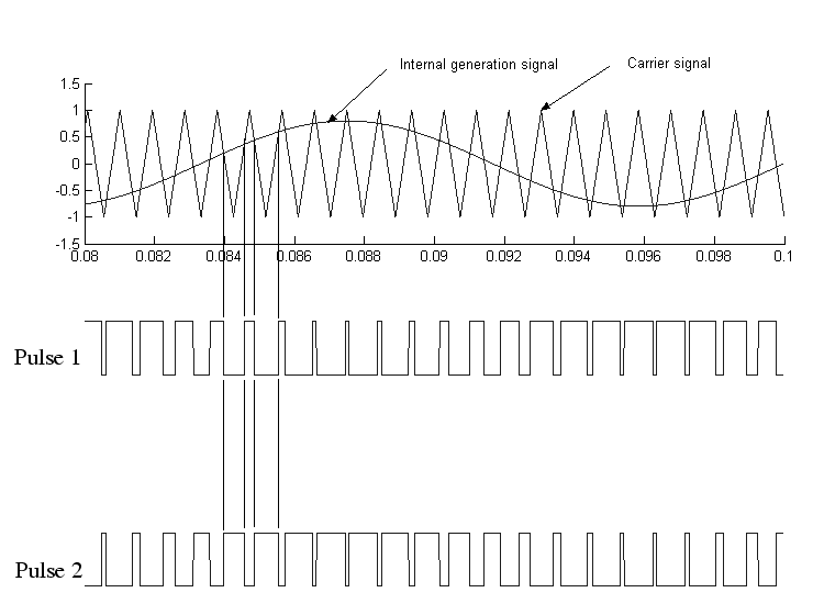
The triangular carrier signal is compared to the sinusoidal reference signal. Each time the two signals become equal (at each crossing point), the value of the pulses passes from 0 to 1, or 1 to 0, depending on their previous value.
The following figure displays the six pulses generated by the PWM Generator block when programmed to control a three-arm bridge.
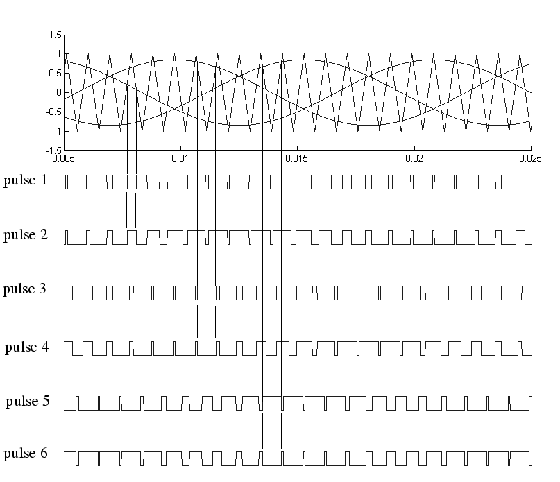
Pulse 2 is the complement of pulse1, pulse 4 the complement of pulse 3, and pulse 6 the complement of pulse 5. Note that, unlike the pulses generated by the Synchronized 6-Pulse Generator block, the pulses generated by the PWM Generator block are of variable width.
Dialog Box and Parameters
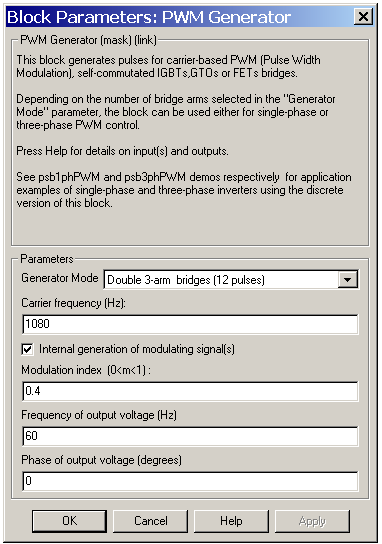
- Generator Mode
- Specify the number of pulses to generate. The number of pulses is proportional to the number of bridge arms to fire. Select for example Double 3-arm bridges (12 pulses) to fire the self-commuted devices of two six-pulse bridges connected in a twelve-pulse bridge configuration.
- Carrier frequency (Hz)
- The frequency, in hertz, of the carrier triangular signal.
- Internal generation of modulating signal (s)
- If selected, the modulating signal is generated by the block. Otherwise, external signals are used for pulse generation.
- Modulation index (0 < m < 1)
- The amplitude of the reference internal signal. The Modulation index must be greater than 0, and lower than or equal to 1. This parameter is used to control the amplitude of the output voltage of the controlled bridge.
- The Modulation index parameter is visible only if the Internal generation of modulating signal (s) parameter is selected.
- Frequency of output voltage (Hz)
- The frequency, in hertz, of the reference internal signal. This parameter is used to control the frequency of the output voltage of the controlled bridge. The Frequency of output voltage (Hz) parameter is visible only if the Internal generation of modulating signal (s) parameter is selected.
- Phase of output voltage (degrees)
- The phase, in degrees, of the reference internal signal. This parameter is used to control the phase of the output voltage of the controlled bridge. The Phase of output voltage parameter is visible only if the Internal generation of modulating signal (s) parameter is selected.
Inputs and Outputs
- signal(s)
- The input is the reference sinusoidal voltage when Internal generation of modulating signal is not selected. Connect this input to a single-phase sinusoidal signal when the block is used to control a single- or a two-arm bridge, or to a three-phase sinusoidal signal when the PWM Generator block is controlling one or two three-phase bridges. The input can be left unconnected when Internal generation of modulating signal (s) is selected.
- Pulses
- The output contains the two, four, six, or twelve pulse signals used to fire the self-commuted devices (MOSFETs, GTOs, or IGBTs) of single-phase, two-phase, three-phase, or a combination of two three-phase bridges.
Example
See psb1phPWM and psb3phPWM demos for examples of single-phase and three-phase inverters.
 | Powergui | | RMS |  |


