
| SimPowerSystems |   |
Model the dynamics of a three-phase permanent magnet synchronous machine with sinusoidal flux distribution
Library
Description![]()
The Permanent Magnet Synchronous Machine block operates in either generating or motoring mode. The mode of operation is dictated by the sign of the mechanical torque (positive for motoring, negative for generating). The electrical and mechanical parts of the machine are each represented by a second-order state-space model. The model assumes that the flux established by the permanent magnets in the stator is sinusoidal, which implies that the electromotive forces are sinusoidal.
The block implements the following equations expressed in the rotor reference frame (qd frame).
Electrical System
where (all quantities in the rotor reference frame, referred to the stator)
 r: Angular velocity of the rotor
 : Amplitude of the flux induced by the permanent magnets of the rotor in the stator phases
Mechanical System
 : Rotor angular position
Dialog Box and Parameters
 ).
). (Wb) induced in the stator windings by the magnets.
Inputs and Outputs
The first three inputs are the electrical connections of the machine's stator. The fourth input is the mechanical torque at the machine's shaft (Simulink signal). This input should normally be positive because the Permanent Magnet Synchronous Machine block is usually used as a motor. Nevertheless, you can apply a negative torque input if you choose to use the block in generating mode.
The block outputs a vector containing the following 10 variables (all currents flowing into machine):
 r, in rad/s
 , in rad
You can demultiplex these variables by using the Machines Measurement Demux block provided in the Machines library.
Assumption
The Permanent Magnet Synchronous Machine block assumes a linear magnetic circuit with no saturation of the stator and rotor iron. This assumption can be made because of the large air gap usually found in permanent magnet synchronous machines.
Example
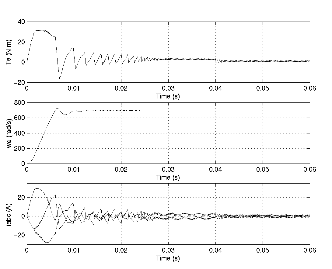
This psbpmmotor.mdl demo illustrates the use of the Permanent Magnet Synchronous Machine block in motoring mode with a closed-loop control system built entirely in Simulink. The interfacing is done using Controlled Voltage Source blocks from the Electrical Sources library. The complete system consists of a PWM inverter built with ideal switches (Simulink Relay blocks). Two control loops are used; the inner loop is used to regulate the motor line currents and the outer loop regulates the motor's speed. More elaborate and efficient control schemes for the Permanent Magnet Synchronous Machine block can be found, for instance, in [1]. The mechanical torque applied at the motor's shaft is originally 3 N.m (nominal) and steps to 1 N.m at t = 0.04 seconds. The parameters of the machine are those found in the dialog box section.
Set the simulation parameters as follows:
ode15s
Run the simulation and observe the motor's torque, speed, and currents.
The torque climbs to nearly 32 N.m when the motor starts but stabilizes rapidly to its nominal value (3 N.m), until the step is applied, at which point the torque oscillates slightly before stabilizing to its new value (1 N.m). As for the speed, you can see that it stabilizes quite fast at start-up and is not affected by the load step.
The currents are initially high when the machine starts, like the torque, but stabilize quickly to their nominal values, until the step is applied, at which point they oscillate before stabilizing to a lower value, corresponding to the load torque decrease.
References
[1] Grenier D., L.-A. Dessaint, O. Akhrif, Y. Bonnassieux, and B. LePioufle, "Experimental Nonlinear Torque Control of a Permanent Magnet Synchronous Motor Using Saliency," IEEE Transactions on Industrial Electronics, Vol. 44, No. 5, October 1997, pp. 680-687.
 | Parallel RLC Load | PI Section Line |  |