| SimPowerSystems |
  |
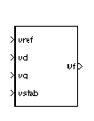
Excitation System
Provide an excitation system for the synchronous machine and regulate its terminal voltage in generating mode
Library
Machines
Description
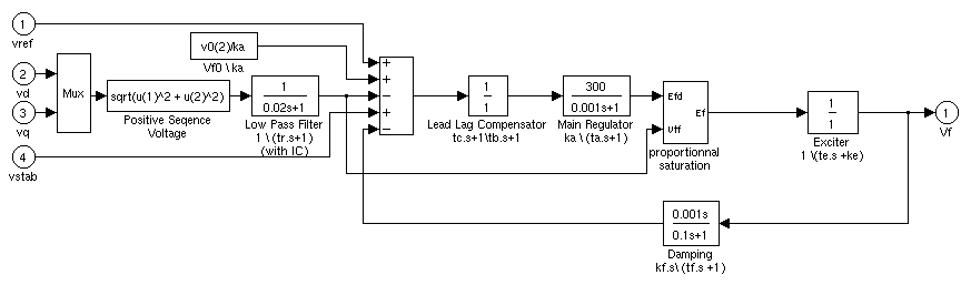
The Excitation System block is a Simulink system implementing a DC exciter described in [1], without the exciter's saturation function. The basic elements that form the Excitation System block are the voltage regulator and the exciter.
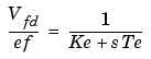
The exciter is represented by the following transfer function between the exciter voltage Vfd and the regulator's output ef:
Dialog Box and Parameters
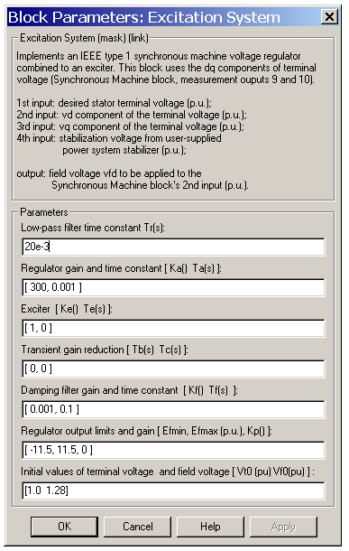
- Low-pass filter time constant
- The time constant Tr, in seconds (s), of the first-order system that represents the stator terminal voltage transducer.
- Regulator
- The gain Ka and time constant Ta, in seconds (s), of the first-order system representing the main regulator.
- Exciter
- The gain Ke and time constant Te, in seconds (s), of the first-order system representing the exciter.
- Transient gain reduction time constants
- The time constants Tb, in seconds (s), and Tc, in seconds (s), of the first-order system representing a lead-lag compensator.
- Damping filter
- The gain Kf and time constant Tf, in seconds (s), of the first-order system representing a derivative feedback.
- Regulator output limits
- Limits Efmin and Efmax are imposed on the output of the voltage regulator. The upper limit can be constant and equal to Efmax, or variable and equal to the rectified stator terminal voltage Vtf times a proportional gain Kp. If Kp is set to 0, the former applies. If Kp is set to a positive value, the latter applies.
- Initial conditions
- The initial values of terminal voltage Vt0 (p.u.) and field voltage Vf0 (p.u.). When set correctly, they allow you to start the simulation in steady state. Initial terminal voltage should normally be set to 1 p.u. Initial field voltage can be computed by the load flow utility of the Powergui block.
Example
See the Hydraulic Turbine and Governor block.
Inputs and Outputs
The first input of the block is the desired value of the stator terminal voltage. The following two inputs are the vq and vd components of the terminal voltage. The fourth input can be used to provide additional stabilization of power system oscillations. All inputs are in p.u. The output of the block is the field voltage Vf for the Synchronous Machine block (p.u.).
References
[1] "Recommended Practice for Excitation System Models for Power System Stability Studies," IEEE Standard 421.5-1992, August, 1992.
See Also
Hydraulic Turbine and Governor, Steam Turbine and Governor, Synchronous Machine
| | dq0_to_abc Transformation | | Fourier | |