| SimPowerSystems | |
Implement a circuit breaker opening at the current zero crossing
Library
Description
The Breaker block implements a circuit breaker where the opening and closing times can be controlled either from an external Simulink signal (external control mode), or from an internal control timer (internal control mode).
The arc extinction process is simulated by opening the breaker device when the current passes through 0 (first current zero crossing following the transition of the Simulink control input from 1 to 0).
When the breaker is closed it behaves as a resistive circuit. It is represented by a resistance Ron. The Ron value can be set as small as necessary in order to be negligible compared with external components (typical value is 10 m ). When the breaker is open it has an infinite resistance.
If the Breaker block is set in external control mode, a Simulink input appears on the block icon. The control signal connected to the Simulink input must be either 0 or 1: 0 to open the breaker, 1 to close it. If the Breaker block is set in internal control mode, the switching times are specified in the dialog box of the block.
If the breaker initial state is set to 1 (closed), Power System Blockset automatically initializes all the states of the linear circuit and the Breaker block initial current so that the simulation starts in steady state.
A series Rs-Cs snubber circuit is included in the model. It can be connected to the circuit breaker.
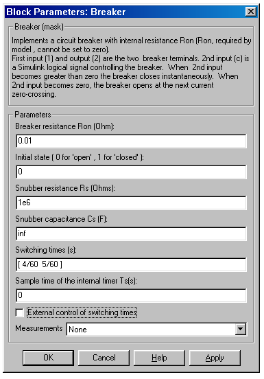
Dialog Box and Parameters
). The Breaker resistance Ron parameter cannot be set to 0.1, and an open contact is displayed when it is set to 0.). Set the Snubber resistance Rs parameter to inf to eliminate the snubber from the model. 0 to eliminate the snubber, or to inf to get a resistive snubber.0 (open), the breaker closes at the first switching time, opens at the second switching time, and so on. The Switching times parameter is not visible in the dialog box if the External control of switching times parameter is selected.0 or 1) connected to the Simulink input.In the Available Measurements list box of the Multimeter block, the measurement is identified by a label followed by the block name:
Measurement
Label
Limitations
When the block is connected in series with an inductor or another current source, you must add the snubber circuit. In most applications you can use a resistive snubber (Snubber capacitance parameter set to inf) with a large resistor value (Snubber resistance parameter set to 1e6, or so). Because of modeling constraints, the internal breaker inductance Ron cannot be set to 0.
You must use a stiff integration algorithm to simulate circuits with the Breaker block. ode23tb or ode15s with default parameters usually gives the best simulation speed.
Example
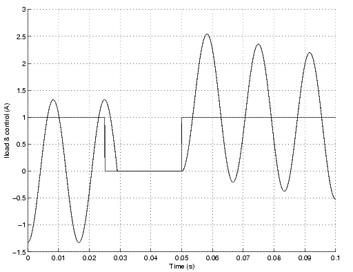
The psbbreaker.mdl demo illustrates a circuit breaker connected in series with a series RL circuit on a 60 Hz voltage source. The switching times of the Breaker block are controlled by a Simulink signal. The breaker device is initially closed and an opening order is given at t = 1.5 cycles, when current reaches a maximum. The current stops at the next zero crossing, then the breaker is reclosed at a zero crossing of voltage at t = 3 cycles.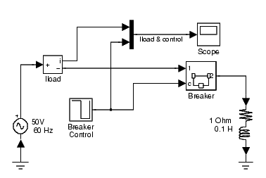
Simulation produces the following results.
Note that the breaker device opens only when the load current has reached zero, after the opening order.
See Also
3-Phase Breaker, 3-Phase Fault
| | Asynchronous Machine | Controlled Current Source | |