| SimPowerSystems |
  |
3-Phase Breaker
Implement a three-phase circuit breaker opening at the current zero crossing
Library
Elements
Description

The 3-Phase Breaker block implements a three-phase circuit breaker where the opening and closing times can be controlled either from an external Simulink signal (external control mode), or from an internal control timer (internal control mode).
The 3-Phase Breaker block uses three Breaker blocks connected between the inputs and the outputs of the block. You can use this block in series with the three-phase element you want to switch. See the Breaker block reference pages for details on the modeling of the single-phase breakers.
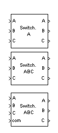
If the 3-Phase Breaker block is set in external control mode, a control input appears in the block icon. The control signal connected to this input must be either 0 or 1, 0 to open the breakers, 1 to close them. If the 3-Phase Breaker block is set in internal control mode, the switching times are specified in the dialog box of the block. The three individual breakers are controlled with the same signal.
Series Rs-Cs snubber circuit are included in the model. They can be optionally connected to the phase breakers. If the 3-Phase Breaker block happens to be in series with an inductive circuit, an open circuit or a current source, you must use the snubbers.
Dialog Box and Parameters

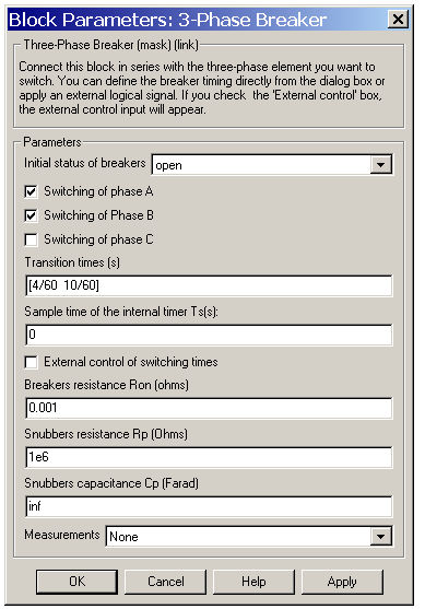
- Initial status of breakers
- The initial status of the breakers. The initial status is the same for the three breakers.
- Switching of phase A
- If selected, the switching of phase A is activated. If not selected, the breaker of phase A stays in its initial status specified in the Initial status of breakers parameter.
- Switching of Phase B
- If selected, the switching of phase B is activated. If not selected, the breaker of phase B stays in its initial status specified in the Initial status of breakers parameter.
- Switching of phase C
- If selected, the switching of phase C is activated. If not selected, the breaker of phase C stays in its initial status specified in the Initial status of breakers parameter.
- Transition times (s)
- Specify the vector of switching times when using the 3-Phase Breaker block in internal control mode. At each transition time the selected breakers opens or closes depending to their initial state. The Transition times (s) parameter is not visible in the dialog box if the External control of switching times parameter is selected.
- Sample time of the internal timer Ts (s):
- The sample time of the internal breakers. The default is 0, corresponding to continuous breaker models.
- External control of switching times
- If selected, adds a fourth input port to the 3-Phase Breaker block for an external control of the switching times of the breakers. The switching times are defined by a Simulink signal (
0-1 sequence).
- Breakers resistance Ron (ohms)
- The internal breaker resistances, in ohms (
 ). The Breaker resistance Ron parameter cannot be set to 0.
- Snubbers resistance Rp (ohms)
- The snubber resistances, in ohms (
 ). Set the Snubber resistance Rp parameter to
 inf to eliminate the snubbers from the model.
- Snubbers capacitance Cp (Farad)
- The snubber capacitances, in farads (F). Set the Snubber capacitance Cp parameter to
0 to eliminate the snubbers, or to inf to get resistive snubbers.
- Measurements
- Select Breaker voltages to measure the voltage across the three internal breaker terminals.
- Select Breaker currents to measure the current flowing through the three internal breakers. If the snubber devices are connected, the measured currents are the ones flowing through the breakers contacts only.
- Select Breaker voltages and currents to measure the breaker voltages and the breaker currents.
- Place a Multimeter block in your model to display the selected measurements during the simulation. In the Available Measurements list box of the Multimeter block, the measurements is identified by a label followed by the block name and the phase:
Measurement
|
Label
|
Breaker voltages
|
Ub <block name> /Breaker A: Ub <block name> /Breaker B:
Ub <block name> /Breaker C.
|
Breaker currents
|
Ib <block name> /Breaker A: Ib <block name> /Breaker B:
Ib <block name> Breaker C.
|
Inputs and Outputs
The inputs 1,2 and 3 and the three outputs are the breaker terminals. The breaker A is connected between the input and output 1, the breaker B is connected between input and output 2, and the breaker C is connected between input and output 3. If the 3-Phase Breaker block is set in external control mode, the input 4 appears and it is used to control the opening and closing of the three internal breakers.
Example
See the psb3phlinereclose.mdl and psb3phseriescomp.mdl circuits for demos using the 3-Phase Breaker block.
See also
Breaker, 3-Phase Fault
 | Synchronous Machine | | 3-Phase Dynamic Load |  |


 ). The Breaker resistance Ron parameter cannot be set to 0.
 ). Set the Snubber resistance Rp parameter to
