| SimPowerSystems | |
Measure the active and reactive powers of a voltage-current pair
Library
Description
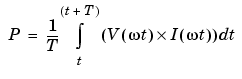
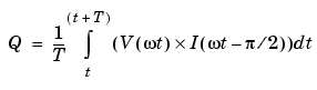
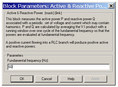
The Active & Reactive Power block measures the active power P and reactive power Q associated with a periodic voltage-current pair that can contain harmonics. P and Q are calculated by averaging the V I product with a running window over one cycle of the fundamental frequency, so that the powers are evaluated at fundamental frequency.
where T = 1/(fundamental frequency).
A current flowing into an RL branch, for example, produces positive active and reactive powers.
Dialog Box and Parameters
Inputs and Outputs
The first input is the instantaneous voltage. The second input is the instantaneous current. The output is a vector [P Q] of the active and reactive powers.
Example
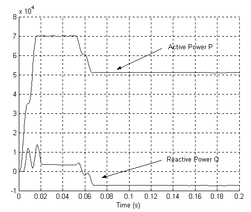
The psbtransfo.mdl demo simulates a three-winding distribution transformer rated at 75 kVA - 14400/120/120 V. The transformer primary winding is connected to a high-voltage source of 14400 Vrms. Two identical inductive loads (20 kW-10 kvar) are connected to the two secondary windings. A third capacitive load (30 kW-20 kvar) is fed at 240 V. 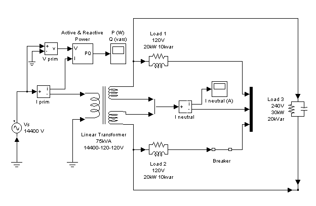
Initially, the circuit breaker in series with Load 2 is closed, so that the system is balanced. When the circuit breaker opens, a current starts to flow in the neutral path as a result of the load unbalance.
The active power computed from the primary voltage and current is measured by an Active & Reactive Power block.
When the breaker opens, the active power decreases from 70 kW to 50 kW.
| | AC Current Source | AC Voltage Source | |