| Embedded Target for Motorola MPC555 |
  |
CAN Message Unpacking (CANdb)
Decompose a CAN message into its constituent signals
Library
CAN Message Blocks
Description

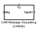
The CAN Message Unpacking (CANdb) block complements the CAN Message Packing (CANdb) block. The user interface for the block is almost identical. The difference is that the CAN Message Unpacking (CANdb) block accepts a CAN message as an input and decomposes it into individual signals.
Note that the CAN Message Blocks blocks library provides the CAN Message Unpacking (CANdb) block embedded in a Fcn Call subsystem, as shown in this figure.When a message is received, a trigger should be provided to initiate unpacking of the message.

Dialog Box

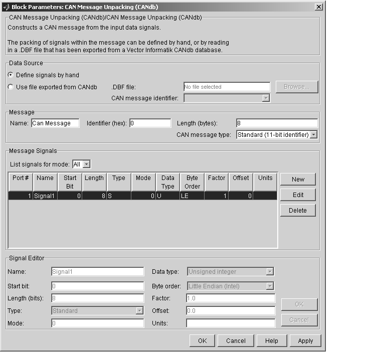
There are four panels to the CAN Message Unpacking (CANdb) dialog box.
Data Source Panel
Specify whether you want to define the message composition by hand or retrieve a message composition specification from a CANdb database. CANdb is a standard controlled by Vector-Informatik. To use CANdb you will need to purchase a copy from Vector-Informatik.
The software cannot read the CANdb format file directly. Instead in CANdb you must export the file as a DBASE (.dbf) format file and place it in your working directory.
- Define signals by hand
- When you select Define signals by hand, the Message, Message Signals, and Signal Editor panels are activated. You can then edit the message characteristics manually.
- Use file exported from CANdb
- Select this option if you want to retrieve a message composition specification from a CANdb database. Before using this feature, you must configure an ODBC data source and locate your database files in the MATLAB work directory. The procedure for doing this is given in Configuring the ODBC Data Source for CANdb Blocks.
- When you select Use file exported from CANdb, the Browse... button and .DBF file field become active. You can then select a database file by browsing for it or by entering the filename in the .DBF file field. After you have selected a database file, the CAN message identifier menu displays a list of available messages in the database. Select the desired message.
Message Panel
Contains information that applies to the whole message.
- Name
- Name of the message
- Identifier (hex)
- The hexidecimal number that identifies the message on the CAN bus.
- Length
- Length of the message, in bytes.
- CAN message type
- Select either
Standard(11-bit identifier) or Extended(29-bit identifier).
Message Signals Panel
Provides a display-only list of information for each input signal to be packed into the message. The signal parameters displayed in this list are described in the Signal Editor Panel section below.
In addition to the list of signals, this panel contains three buttons:
- The New button lets you create a signal, which you can then edit in the Signal Editor.
- The Edit button activates the Signal Editor panel. This panel lets you edit the parameters of the selected signal.
- The Delete button lets you delete a signal.
The List Signals for Mode menu lets you restrict the list of signals to display only those signals with a given mode value. (See Type and Mode). By default, List Signals for Mode is set to display all signals regardless of mode value.
The Port# column displays the number of each input signal. The number indicates the order in which the signals enter the Simulink block, from top to bottom.
The other columns display properties described in Signal Editor Panel.
Signal Editor Panel
Lets you enter or change parameter values for the selected signal. To edit a signal, select it in the Message Signals Panel, and then click the Edit button. The Signal Editor panel will become active. After you have made the required changes to the signal, click Apply or OK to commit your changes. Click Cancel to finish editing without retaining changes.
Each parameter is described briefly here. Each signal is defined according to the CANdb standard; refer to your CANdb documentation for detailed information.
- Name
- The name of the signal that you see displayed in the CANdb and on the Simulink block.
- Start bit
- Bit position, in the data bytes, where the signal is inserted.
- Length (bits)
- The number of bits to be used in the message
- Type and Mode
- More than one signal can be mapped to the same location in a message. To determine which message is actually mapped, you can define at most one mode signal. The mode signal is an integer valued input. You can then define as many mode-dependent signals as you want. A mode-dependent signal also makes use of the Mode value.The Mode value is matched against the mode signal. If the Mode value equals the value of the mode signal then the signal is packed into the message. If it does not match then the signal is ignored.
- Mode Value
- See Type and Mode above.
- Data type
- This menu allows you to specify whether the bits allocated to a signal are interpreted as a signed (twos complement) or unsigned integer. For example, consider a 3-bit signal where all bits are set to 1. If the signal is interpreted as signed, it would represent the value -1 before scaling and offsetting. If the signal is interpreted as unsigned, it would represent the value 7 (
0x7h) before scaling and offsetting.
- Byte order
- Select one of the following options:
Big Endian (Motorola): the start bit is the least significant bit of the least significant byte from the end of the message. Bytes are counted left from here.
Little Endian (Intel): the start bit is the least significant bit of the least significant byte from the beginning of the message. Bytes are counted right from here.
- The CAN Message Unpacking (CANdb) block uses Motorola Backwards big endian format, which is the default for CANdb. It does not uses Motorola Forwards big endian format, which is the default for CANdb++.
- For more detailed descriptions of byte layout see your CANdb documentation.
- Factor and Offset
- Define the Factor and Offset values in the formula for conversion between the physical value (Simulink signal value) and the data stored in the packet. The conversion formula is defined as
Phys_value = (Raw_value * Factor + Offset)
Where Raw_value is the value stored in the packet. Note that the Raw_value may be signed or unsigned depending on the Data type.
- Units
This field is informational only. If desired, enter the appropriate units for the signal.
 | CAN Message Unpacking | | MIOS Digital In |  |


