
| Mapping Toolbox |   |
The Origin Vector
A map axes Origin property is a vector describing the geometry of the displayed projection. The form of this vector is of the following:
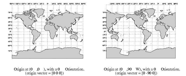
The latitude and longitude represent the geographic coordinates of the center point of the display from which the projection is calculated. The orientation refers to the angle from straight up at which the North Pole bears from this center point. The default origin vector is [0 0 0], that is, the projection is centered on the geographic point (0°,0°) and the North Pole is straight up from this point. Such a display is in a normal aspect. In fact, changes to only the longitude value of the origin vector do not change the aspect; a normal aspect is one centered on the Equator in latitude with an orientation of 0°.
Both of these Miller projections have normal aspects, despite having different origin vectors:

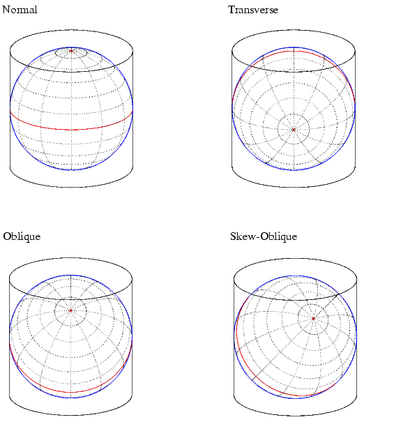
This makes sense if you think about a simple, true cylindrical projection. This is the projection of the globe onto a cylinder wrapped around it. For normal aspects, this cylinder is tangent to the globe at the Equator, and changing the origin longitude simply corresponds to rotating the sphere about the longitudinal axis of the cylinder. If we continue with the wrapped-cylinder model, we can understand the other aspects as well.
Following this description, a transverse projection can be thought of as a cylinder wrapped around the globe tangent at the poles and along a meridian. Finally, when such a cylinder is tangent along an arbitrary great circle, the result is an oblique projection.
Here are diagrams of the four cylindrical map orientations, or aspects:

Of course, few projections are actually true cylindrical projections, but the concept of the wrapped cylinder is nonetheless a convenient way to think about it. Perhaps the best way to gain an appreciation for projection aspect is to look at a few examples.
Here, a psuedocylindrical projection, the Sinusoidal, is used. First, look at the normal aspect of this projection:
In the normal aspect, the North Pole is at the top of the image. To create a transverse aspect, imagine pulling the North Pole down to the center of the image, which was originally occupied by the point (0°,0°).
The shape of the frame is unaffected; this is still a Sinusoidal projection:
The normal and transverse aspects can be thought of as limiting conditions. Anything else is an oblique aspect. Conceptually, if you push the North Pole halfway back to its original position, that is, to the position originally occupied by the point (45°N, 0°) in the normal aspect, the result will be a simple oblique aspect.
Here is the oblique aspect Sinusoidal projection:
Another way of understanding this is to imagine the new origin point (45°N,0°) being pulled to the center of the image, to the point originally occupied by (0°,0°) in the normal aspect.
The examples so far have left the aspect orientation at 0°. If the orientation is altered, an oblique aspect becomes a skew-oblique. Imagine the previous example with an orientation of 45°. Conceptually, the skew-oblique aspect corresponds to pulling the new origin point, (45°N,0°) down to the center of the projection and then rotating the projection until the North Pole lies at an angle of 45° clockwise from straight up with respect to the new origin.
Any projection can be viewed in alternate aspects. Some of these are quite useful. For example, the transverse aspect of the Mercator projection is widely used in cartography, especially for mapping regions with predominantly north-south extent. One candidate for such handling might be Chile. Oblique Mercator projections might be used to map long regions that run neither north and south nor east and west, such as New Zealand.
The features of a projection are maintained in any aspect, relative to the base projection. As we have seen, the outline, or frame doesn't change. Non-directional features also do not change. For example, the Sinusoidal projection is equal-area, and is so in any aspect. Directional features must be considered carefully, however. In the normal aspect of the Sinusoidal projection, scale is true along every parallel and the central meridian. This is not the case for the skew-oblique aspect; however, scale is true along the lines where these parallels and meridian would be in the corresponding base projection.
The base projection can be thought of as a standard coordinate system, and the normal aspect conforms to it. The other aspects can be thought of as coordinate transformations.
A standard method of visualizing the distortions introduced by the map projection is to display small circles at regular intervals across the globe. After projection, the small circles appear as ellipses of various sizes, elongations, and orientations. The sizes and shapes of the ellipses reflect the projection distortions. Conformal projections have circular ellipses, while equal area projections have ellipses of the same area. This method was invented by Tissot, and the ellipses are called Tissot indicatrices in his honor. You can add the indicatrices to a map display with the command tissot and remove them with clmo Tissot.
For a more quantitative look at the projection distortion, use mdistort. This function draws contour lines of constant scale, area, and angular distortion on the map. This is useful in selecting projections and projection parameters to keep distortion within limits. Here are the lines of percent scale distortion for the skew-oblique Sinusoidal projection. The lines of zero distortion along the axes of the base projection are apparent in the contour plot.
 | Projection Aspect | Coordinate Transformations |  |