| Instrument Control Toolbox |
  |
GPIB Lines
The GPIB consists of 24 lines, which are shared by all instruments connected to the bus. 16 lines are used for signals, while 8 lines are for ground. The signal lines are divided into these groups:
- Eight data lines
- Five interface management lines
- Three handshake lines
The signal lines use a low-true (negative) logic convention with TTL levels. This means that a line is low (true or asserted) when it is a TTL low level, and a line is high (false or unasserted) when it is a TTL high level. The pin assignment scheme for a GPIB connector is shown below.
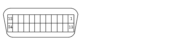
The pins and signals associated with the GPIB connector are described below.
Table 3-1: GPIB Pin and Signal Assignments
Pin
|
Label
|
Signal Name
|
Pin
|
Label
|
Signal Name
|
1
|
DIO1
|
Data transfer
|
13
|
DIO5
|
Data transfer
|
2
|
DIO2
|
Data transfer
|
14
|
DIO6
|
Data transfer
|
3
|
DIO3
|
Data transfer
|
15
|
DIO7
|
Data transfer
|
4
|
DIO4
|
Data transfer
|
16
|
DIO8
|
Data transfer
|
5
|
EOI
|
End Or Identify
|
17
|
REN
|
Remote Enable
|
6
|
DAV
|
Data Valid
|
18
|
GND
|
DAV ground
|
7
|
NRFD
|
Not Ready For Data
|
19
|
GND
|
NRFD ground
|
8
|
NDAC
|
Not Data Accepted
|
20
|
GND
|
NDAC ground
|
9
|
IFC
|
Interface Clear
|
21
|
GND
|
IFC ground
|
10
|
SRQ
|
Service Request
|
22
|
GND
|
SRQ ground
|
11
|
ATN
|
Attention
|
23
|
GND
|
ATN ground
|
12
|
Shield
|
Chassis ground
|
24
|
GND
|
Signal ground
|
Data Lines
The eight data lines, DIO1 through DIO8, are used for transferring data one byte at a time. DIO1 is the least significant bit, while DIO8 is the most significant bit. The transferred data can be an instrument command or a GPIB interface command.
Data formats are vendor-specific and can be text-based (ASCII) or binary. GPIB interface commands are defined by the IEEE 488 standard.
Interface Management Lines
The interface management lines control the flow of data across the GPIB interface, and are described below.
Table 3-2: GPIB Interface Management Lines
Line
|
Description
|
ATN
|
Used by the Controller to inform all devices on the GPIB that bytes are being sent. If the ATN line is high, the bytes are interpreted as an instrument command. If the ATN line is low, the bytes are interpreted as an interface message.
|
IFC
|
Used by the Controller to initialize the bus. If the IFC line is low, the Talker and Listeners are unaddressed, and the System Controller becomes the Controller-In-Charge.
|
REN
|
Used by the Controller to place instruments in remote or local program mode. If REN is low, all Listeners are placed in remote mode, and you cannot change their settings from the front panel. If REN is high, all Listeners are placed in local mode.
|
SRQ
|
Used by Talkers to asynchronously request service from the Controller. If SRQ is low, then one or more Talkers require service (for example, an error such as invalid command was received). You issue a serial poll to determine which Talker requested service. The poll automatically sets the SRQ line high.
|
EOI
|
If the ATN line is high, the EOI line is used by Talkers to identify the end of a byte stream such as an instrument command. If the ATN line is low, the EOI line is used by the Controller to perform a parallel poll (not supported by the toolbox).
|
You can examine the state of the interface management lines with the BusManagementStatus property.
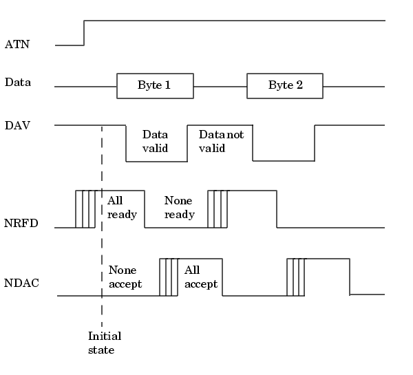
Handshake Lines
The three handshake lines, DAV, NRFD, and NDAC, are used to transfer bytes over the data lines from the Talker to one or more addressed Listeners.
Before data is transferred, all three lines must be in the proper state. The active Talker controls the DAV line and the Listener(s) control the NRFD and NDAC lines. The handshake process allows for error-free data transmission. The handshake lines are described below.
Table 3-3: GPIB Handshake Lines
Line
|
Description
|
DAV
|
Used by the Talker to indicate that a byte can be read by the Listeners.
|
NRFD
|
Indicates whether the Listener is ready to receive the byte.
|
NDAC
|
Indicates whether the Listener has accepted the byte.
|
The handshaking process follows these steps:
- Initially, the Talker holds the DAV line high indicating no data is available, while the Listeners holds the NRFD line high and the NDAC line low indicating it is ready for data and no data is accepted, respectively.
- When the Talker puts data on the bus, it sets the DAV line low, which indicates that the data is valid.
- The Listeners set the NRFD line low, which indicates that they are not ready to accept new data.
- The Listeners set the NDAC line high, which indicates that the data is accepted.
- When all Listeners indicate that they have accepted the data, the Talker asserts the DAV line indicating that the data is no longer valid. The next byte of data can now be transmitted.
- The Listeners hold the NRFD line high indicating they are ready to receive data again, and the NDAC line is held low indicating no data is accepted.
| Note
If the ATN line is high during the handshaking process, the information is considered data such as an instrument command. If the ATN line is low, the information is considered a GPIB interface message.
|
The handshaking steps are shown below.
You can examine the state of the handshake lines with the HandshakeStatus property.
| | Important GPIB Features | | Status and Event Reporting | |