
| Function Reference |   |
Feedback connection of two LTI models
Syntax
sys = feedback(sys1,sys2)
sys = feedback(sys1,sys2,sign)
sys = feedback(sys1,sys2,feedin,feedout,sign)
Description
sys = feedback(sys1,sys2)
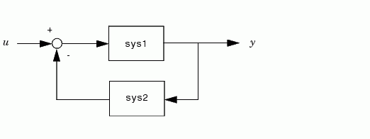
returns an LTI model sys for the negative feedback interconnection.

The closed-loop model sys has  as input vector and
  as output vector. The LTI models
 sys1 and sys2 must be both continuous or both discrete with identical sample times. Precedence rules are used to determine the resulting model type (see Precedence Rules).
To apply positive feedback, use the syntax
By default, feedback(sys1,sys2) assumes negative feedback and is equivalent to feedback(sys1,sys2,-1).
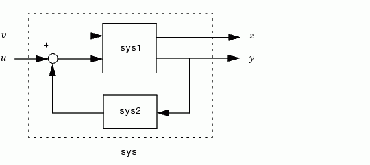
computes a closed-loop model sys for the more general feedback loop.

The vector feedin contains indices into the input vector of sys1 and specifies which inputs  are involved in the feedback loop. Similarly,
 feedout specifies which outputs  of
of sys1 are used for feedback. The resulting LTI model sys has the same inputs and outputs as sys1 (with their order preserved). As before, negative feedback is applied by default and you must use
For more complicated feedback structures, use append and connect.
Remark
You can specify static gains as regular matrices, for example,
However, at least one of the two arguments sys1 and sys2 should be an LTI object. For feedback loops involving two static gains k1 and k2, use the syntax


G = tf([2 5 1],[1 2 3],'inputname','torque',...
                              'outputname','velocity');
H = zpk(-2,-10,5)
Cloop = feedback(G,H)
Zero/pole/gain from input "torque" to output "velocity":
0.18182 (s+10) (s+2.281) (s+0.2192)
-----------------------------------
 (s+3.419) (s^2 + 1.763s + 1.064)
The result is a zero-pole-gain model as expected from the precedence rules. Note that Cloop inherited the input and output names from G.
Example 2
Consider a state-space plant P with five inputs and four outputs and a state-space feedback controller K with three inputs and two outputs. To connect outputs 1, 3, and 4 of the plant to the controller inputs, and the controller outputs to inputs 4 and 2 of the plant, use
Example 3
You can form the following negative-feedback loops

Limitations
The feedback connection should be free of algebraic loop. If  and
and  are the feedthrough matrices of
 sys1 and sys2, this condition is equivalent to:
See Also
series
parallel
connect
 | evalfr | filt |  |