| Communications Blockset | |
Example: Soft-Decision Decoding
This example creates a rate 1/2 convolutional code. It uses a quantizer and the Viterbi Decoder block to perform soft-decision decoding. This description covers these topics:
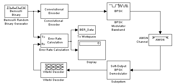
Overview of the Simulation
The model is in the following figure. To open the model, click here in the MATLAB Help browser. The simulation creates a random binary message signal, encodes the message into a convolutional code, modulates the code using the binary phase shift keying (BPSK) technique, and adds white Gaussian noise to the modulated data in order to simulate a noisy channel. Then, the simulation prepares the received data for the decoding block and decodes. Finally, the simulation compares the decoded information with the original message signal in order to compute the bit error rate. The simulation ends after processing 100 bit errors or 107 message bits, whichever comes first.
Defining the Convolutional Code
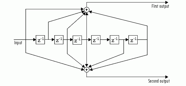
The feedforward convolutional encoder in this example is depicted below.
The encoder's constraint length is a scalar since the encoder has one input. The value of the constraint length is the number of bits stored in the shift register, including the current input. There are six memory registers and the current input is one bit. Thus the constraint length of the code is 7.
The code generator is a 1-by-2 matrix of octal numbers because the encoder has one input and two outputs. The first element in the matrix indicates which input values contribute to the first output, and the second element in the matrix indicates which input values contribute to the second output.
For example, the first output in the encoder diagram is the modulo-2 sum of the rightmost and the four leftmost elements in the diagram's array of input values. The seven-digit binary number 1111001 captures this information, and is equivalent to the octal number 171. The octal number 171 thus becomes the first entry of the code generator matrix. Here, each triplet of bits uses the leftmost bit as the most significant bit. The second output corresponds to the binary number 1011011, which is equivalent to the octal number 133. The code generator is therefore [171 133].
The Trellis structure parameter in the Convolutional Encoder block tells the block which code to use when processing data. In this case, the poly2trellis function, in the Communications Toolbox, converts the constraint length and the pair of octal numbers into a valid trellis structure.
Notice that while the message data entering the Convolutional Encoder block is a scalar bit stream, the encoded data leaving the block is a stream of binary vectors of length 2.
Mapping the Received Data
The received data, that is, the output of the AWGN Channel block, consists of complex numbers that are close to -1 and 1. In order to reconstruct the original binary message, the receiver part of the model must decode the convolutional code. The Viterbi Decoder block in this model expects its input data to be integers between 0 and 7. The demodulator, a custom subsystem in this model, transforms the received data into a format that the Viterbi Decoder block can interpret properly. More specifically, the demodulator subsystem:
The combination of this mapping and the Viterbi Decoder block's decision mapping reverses the BPSK modulation that the BPSK Modulator Baseband block performs on the transmitting side of this model. To examine the demodulator subsystem in more detail, double-click the icon labeled Soft-Output BPSK Demodulator.
Decoding the Convolutional Code
After the received data is properly mapped to length-2 vectors of 3-bit decision values, the Viterbi Decoder block decodes it. The block uses a soft-decision algorithm with 23 different input values because the Decision type parameter is Soft Decision and the Number of soft decision bits parameter is 3.
Soft-Decision Interpretation of Data. When the Decision type parameter is set to Soft Decision, the Viterbi Decoder block requires input values between 0 and 2b-1, where b is the Number of soft decision bits parameter. The block interprets 0 as the most confident decision that the codeword bit is a 0 and interprets 2b-1 as the most confident decision that the codeword bit is a 1. The values in between these extremes represent less confident decisions. The following table lists the interpretations of the eight possible input values for this example.
Traceback and Decoding Delay. The Traceback depth parameter in the Viterbi Decoder block represents the length of the decoding delay. Typical values for a traceback depth are about five or six times the constraint length, which would be 35 or 42 in this example. However, some hardware implementations offer options of 48 and 96. This example chooses 48 because that is closer to the targets (35 and 42) than 96 is.
Delay in Received Data
The Error Rate Calculation block's Receive delay parameter is nonzero because a given message bit and its corresponding recovered bit are separated in time by a nonzero amount of simulation time. The Receive delay parameter tells the block which elements of its input signals to compare when checking for errors.
In this case, the Receive delay value is 49 samples, which is one more than the Traceback depth value (48) in the Viterbi Decoder block. The extra one-sample delay comes from the initial delay in the Buffer block. Because the Buffer block must collect two scalar samples before it can output one vector, its first meaningful output occurs at time 1 second, not time 0.
Comparing Simulation Results with Theoretical Results
This section describes how to compare the bit error rate in this simulation with the bit error rate that would theoretically result from unquantized decoding. The process includes a few steps, described in these sections:
Computing Theoretical Bounds for the Bit Error Rate. To calculate theoretical bounds for the bit error rate Pb of the convolutional code in this model, you can use this estimate based on unquantized-decision decoding:
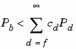
In this estimate, cd is the sum of bit errors for error events of distance d, and f is the free distance of the code. The quantity Pd is the pairwise error probability, given by
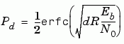
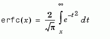
where R is the code rate of 1/2, and erfc is the MATLAB complementary error function, defined by
Values for the coefficients cd and the free distance f are in published articles such as [4]. The free distance for this code is f = 10.
The following commands calculate the values of Pb for Eb/N0 values in the range from 1 to 3.5, in increments of 0.5:
EbNoVec = [1:0.5:4.0];
R = 1/2;
% Errs is the vector of sums of bit errors for
% error events at distance d, for d from 10 to 29.
Errs = [36 0 211 0 1404 0 11633 0 77433 0 502690 0,...
        3322763 0 21292910 0 134365911 0 843425871 0];
% P is the matrix of pairwise error probilities, for
% Eb/No values in EbNoVec and d from 10 to 29.
P = zeros(20,7); % Initialize.
for d = 10:29
   P(d-9,:) = (1/2)*erfc(sqrt(d*R*10.^(EbNoVec/10)));
end
% Bounds is the vector of upper bounds for the bit error
% rate, for Eb/No values in EbNoVec.
Bounds = Errs*P;
Simulating Multiple Times to Collect Bit Error Rates. You can efficiently vary the simulation parameters by using the sim function to run the simulation from the MATLAB command line. For example, the following code calculates the bit error rate at bit energy-to-noise ratios ranging from 1 dB to 4 dB, in increments of 0.5 dB. It collects all bit error rates from these simulations in the matrix BERVec. It also plots the bit error rates in a figure window along with the theoretical bounds computed in the preceding code fragment.
| Note First open the model by clicking here in the MATLAB Help browser. Then execute these commands, which might take a few minutes. |
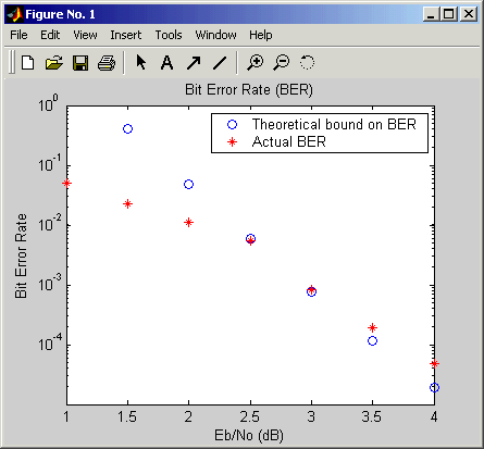
% Plot theoretical bounds and set up figure.
figure;
semilogy(EbNoVec,Bounds,'bo',1,NaN,'r*');
xlabel('Eb/No (dB)'); ylabel('Bit Error Rate');
title('Bit Error Rate (BER)');
legend('Theoretical bound on BER','Actual BER');
axis([1 4 1e-5 1]);
hold on;

BERVec = [];
opts = simset('SrcWorkspace','Current',...
   'DstWorkspace','Current');
% Make the noise level variable.
set_param('doc_softdecision/AWGN Channel',...
    'EsNodB','EbNodB+10*log10(1/2)');
% Simulate multiple times.
for n = 1:length(EbNoVec)
    EbNodB = EbNoVec(n);
    sim('doc_softdecision',5000000,opts);
    BERVec(n,:) = BER_Data;
    semilogy(EbNoVec(n),BERVec(n,1),'r*'); % Plot point.
    drawnow;
end
hold off;
The plot of bit error rate against signal-to-noise ratio follows. The locations of your actual BER points might vary because the simulation involves random numbers.
| | Implementing a Systematic Encoder with Feedback | Selected Bibliography for Convolutional Coding | |