| Communications Blockset | |
Example: A Rate 2/3 Feedforward Encoder
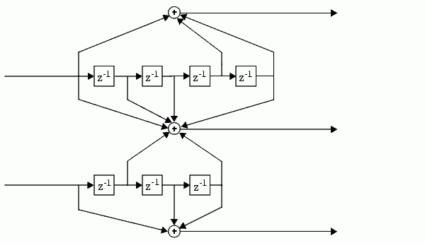
This example uses the rate 2/3 feedforward convolutional encoder depicted in the following figure. The description explains how to determine the coding blocks' parameters from a schematic of a rate 2/3 feedforward encoder. This example also illustrates the use of the Error Rate Calculation block with a receive delay.
How to Determine Coding Parameters. The Convolutional Encoder and Viterbi Decoder blocks can implement this code if their parameters have the appropriate values.
The encoder's constraint length is a vector of length 2 since the encoder has two inputs. The elements of this vector indicate the number of bits stored in each shift register, including the current input bits. Counting memory spaces in each shift register in the diagram and adding one for the current inputs leads to a constraint length of [5 4].
To determine the code generator parameter as a 2-by-3 matrix of octal numbers, use the element in the ith row and jth column to indicate how the ith input contributes to the jth output. For example, to compute the element in the second row and third column, notice that the leftmost and two rightmost elements in the second shift register of the diagram feed into the sum that forms the third output. Capture this information as the binary number 1011, which is equivalent to the octal number 13. The full value of the code generator matrix is [27 33 0; 0 5 13].
To use the constraint length and code generator parameters in the Convolutional Encoder and Viterbi Decoder blocks, use the poly2trellis function to convert those parameters into a trellis structure.
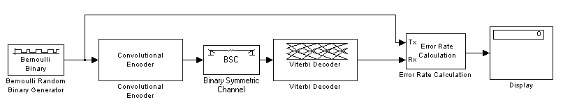
How to Simulate the Encoder. The following model simulates this encoder.
To open the completed model, click here in the MATLAB Help browser. To build the model, gather and configure these blocks:
.5.
randseed function.
.5.
2.
poly2trellis([5 4],[23 35 0; 0 5 13]).
0.02.
randseed function.
poly2trellis([5 4],[23 35 0; 0 5 13]).
68.
100.
Connect the blocks as in the figure. Also, from the model window's Simulation menu, choose Simulation parameters; then in the Simulation Parameters dialog box, set Stop time to inf.
Notes on the model. The matrix size annotations appear on the connecting lines only if you select Signal Dimensions from the model's Format menu. Notice that the encoder accepts a 2-by-1 frame-based vector and produces a 3-by-1 frame-based vector, while the decoder does the opposite. The Samples per frame parameter in the Bernoulli Binary Generator block is 2 because the block must generate a message word of length 2.
Also notice that the Receive delay parameter in the Error Rate Calculation block is 68, which is the vector length (2) of the recovered message times the Traceback depth value (34) in the Viterbi Decoder block. If you examined the transmitted and received signals as matrices in the MATLAB workspace, then you would see that the first 34 rows of the recovered message consist of zeros, while subsequent rows are the decoded messages. Thus the delay in the received signal is 34 vectors of length 2, or 68 samples.
Running the model produces display output consisting of three numbers. The three numbers indicate the error rate, the total number of errors, and the total number of comparisons that the Error Rate Calculation block makes during the simulation. (The first two numbers vary depending on your Initial seed values in the Bernoulli Binary Generator and Binary Symmetric Channel blocks.) The simulation stops after 100 errors occur, because Target number of errors is set to 100 in the Error Rate Calculation block. Note that the error rate is much less than 0.02, the Error probability in the Binary Symmetric Channel block.
| | Parameters for Convolutional Coding | Implementing a Systematic Encoder with Feedback | |