| Communications Blockset |
  |
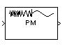
PM Demodulator Passband
Demodulate PM-modulated data
Library
Analog Passband Modulation, in Modulation
Description
The PM Demodulator Passband block demodulates a signal that was modulated using phase modulation. The input is a passband representation of the modulated signal. Both the input and output signals are real sample-based scalar signals.
This block uses a phase-locked loop containing a voltage-controlled oscillator (VCO). The VCO Gain parameter specifies the input sensitivity of the VCO.
In the course of demodulating, the block uses a filter whose transfer function is described by the Lowpass filter numerator and Lowpass filter denominator parameters.
By the Nyquist sampling theorem, the reciprocal of the Sample time parameter must exceed twice the Carrier frequency parameter.
Dialog Box
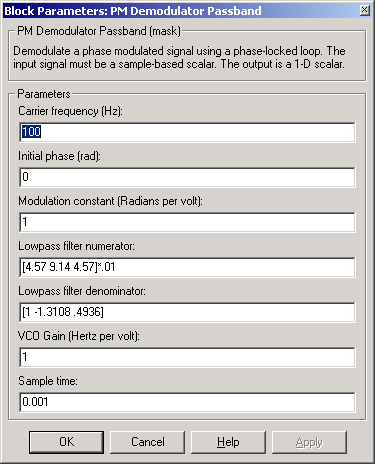
- Carrier frequency (Hz)
- The carrier frequency in the corresponding PM Modulator Passband block.
- Initial phase (rad)
- The carrier signal's initial phase in the corresponding PM Modulator Passband block.
- Modulation constant (Radians per volt)
- The modulation constant in the corresponding PM Modulator Passband block.
- Lowpass filter numerator
- The numerator of the lowpass filter transfer function. It is represented as a vector that lists the coefficients in order of descending powers of s.
- Lowpass filter denominator
- The denominator of the lowpass filter transfer function. It is represented as a vector that lists the coefficients in order of descending powers of s. For an FIR filter, set this parameter to
1.
- VCO Gain (Hertz per volt)
- The input sensitivity of the voltage-controlled oscillator.
- Sample time
- The sample time of the output signal.
Pair Block
PM Modulator Passband
| | PM Demodulator Baseband | | PM Modulator Baseband | |