| Communications Blockset |
  |
PM Demodulator Baseband
Demodulate PM-modulated data
Library
Analog Baseband Modulation, in Modulation
Description

The PM Demodulator Baseband block demodulates a signal that was modulated using phase modulation. The input is a baseband representation of the modulated signal. The input is complex, while the output is real. The input must be a sample-based scalar signal.
This block uses a phase-locked loop containing a voltage-controlled oscillator (VCO). The VCO Gain parameter specifies the input sensitivity of the VCO.
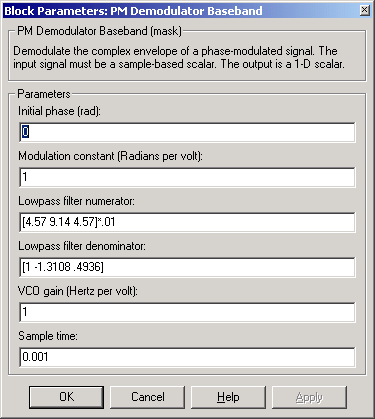
In the course of demodulating, the block uses a filter whose transfer function is described by the Lowpass filter numerator and Lowpass filter denominator parameters.
Dialog Box

- Initial phase (rad)
- The initial phase in the corresponding PM Modulator Baseband block.
- Modulation constant (Radians per volt)
- The modulation constant in the corresponding PM Modulator Baseband block.
- Lowpass filter numerator
- The numerator of the lowpass filter transfer function. It is represented as a vector that lists the coefficients in order of descending powers of s.
- Lowpass filter denominator
- The denominator of the lowpass filter transfer function. It is represented as a vector that lists the coefficients in order of descending powers of s. For an FIR filter, set this parameter to
1.
- VCO gain (Hertz per volt)
- The input sensitivity of the voltage-controlled oscillator.
- Sample time
- The sample time of the output signal.
Pair Block
PM Modulator Baseband
 | Phase Noise | | PM Demodulator Passband |  |


