| Communications Blockset |
  |
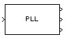
Phase-Locked Loop
Implement a phase-locked loop to recover the phase of the input signal
Library
Synchronization
Description
The Phase-Locked Loop (PLL) block is a feedback control system that automatically adjusts the phase of a locally generated signal to match the phase of an input signal. This block is most appropriate when the input is a narrowband signal.
This PLL has these three components:
- A multiplier used as a phase detector.
- A filter. You specify the filter's transfer function using the Lowpass filter numerator and Lowpass filter denominator mask parameters. Each is a vector that gives the respective polynomial's coefficients in order of descending powers of s.
- To design a filter, you can use functions such as
butter, cheby1, and cheby2 in the Signal Processing Toolbox. The default filter is a Chebyshev type II filter whose transfer function arises from the command below.
[num, den] = cheby2(3,40,100,'s')
- A voltage-controlled oscillator (VCO). You specify characteristics of the VCO using the VCO quiescent frequency, VCO initial phase, and VCO output amplitude parameters.
The input signal represents the received signal. The input must be a sample-based scalar signal. The three output ports produce:
- The output of the filter
- The output of the phase detector
- The output of the VCO
Dialog Box
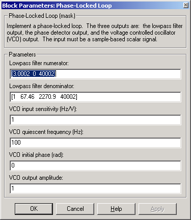
- Lowpass filter numerator
- The numerator of the lowpass filter's transfer function, represented as a vector that lists the coefficients in order of descending powers of s.
- Lowpass filter denominator
- The denominator of the lowpass filter's transfer function, represented as a vector that lists the coefficients in order of descending powers of s.
- VCO input sensitivity (Hz/V)
- This value scales the input to the VCO and, consequently, the shift from the VCO quiescent frequency value. The units of VCO input sensitivity are Hertz per volt.
- VCO quiescent frequency (Hz)
- The frequency of the VCO signal when the voltage applied to it is zero. This should match the carrier frequency of the input signal.
- VCO initial phase (rad)
- The initial phase of the VCO signal.
- VCO output amplitude
- The amplitude of the VCO signal.
See Also
Baseband PLL, Linearized Baseband PLL, Charge Pump PLL
References
For more information about phase-locked loops, see the works listed in Selected Bibliography for Synchronization in Using the Communications Blockset.
| | Phase/Frequency Offset | | Phase Noise | |