| Communications Blockset | |
Permute input symbols using a helical array
Library
Convolutional sublibrary of Interleaving
Description 
The Helical Interleaver block permutes the symbols in the input signal by placing them in an array in a helical fashion and then sending rows of the array to the output port.
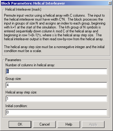
The block uses the array internally for its computations. If C is the Number of columns in helical array parameter, then the array has C columns and unlimited rows. If N is the Group size parameter, then the block accepts an input of length C*N at each time step and partitions the input into consecutive groups of N symbols. Counting from the beginning of the simulation, the block places the kth group in the array along column k mod C. The placement is helical because of the reduction modulo C and because the first symbol in the kth group is in row 1+(k-1)*s, where s is the Helical array step size parameter. Positions in the array that do not contain input symbols have default contents specified by the Initial condition parameter.
The block sends C*N symbols from the array to the output port by reading the next N rows sequentially. At a given time step, the output symbols might be the Initial condition parameter value, symbols from that time step's input vector, or symbols left in the array from a previous time step.
The number of elements of the input vector must be C times N. If the input is frame-based, then it must be a column vector.
Dialog Box
Examples
Suppose that C = 3, N = 2, the Helical array step size parameter is 1, and the Initial condition parameter is -1. After receiving inputs of [1:6]', [7:12]', and [13:19]', the block's internal array looks like the schematic below. The coloring of the inputs and the array indicate how the input symbols are placed within the array. The outputs at the first three time steps are [1; -1; -1; 2; 3; -1], [7; 4; 5; 8; 9; 6], and [13; 10; 11; 14; 15; 12]. (The outputs are not color-coded in the schematic.)
Pair Block
See Also
General Multiplexed Interleaver
References
[1] Berlekamp, E. R. and P. Tong. "Improved Interleavers for Algebraic Block Codes." U. S. Patent 4559625, Dec. 17, 1985.
| | Helical Deinterleaver | Insert Zero | |