
| Aerospace Blockset |   |
Implement a state-space controller in a self-conditioned form
Library
Description
The Self-Conditioned [A,B,C,D] block can be used to implement the state-space controller defined by


The input umeas is a vector of the achieved actuator positions, and the output udem is the vector of controller actuator demands. In the case that the actuators are not limited, then umeas = udem and substituting the output equation into the state equation returns the nominal controller. In the case that they are not equal, the dynamics of the controller are set by the poles of A-HC.
Hence H must be chosen to make the poles sufficiently fast to track umeas but at the same time not so fast that noise on e is propagated to udem. The matrix H is designed by a callback to the Control Systems Toolbox command place.m to place the poles at defined locations.
Dialog Box
Inputs and Outputs
The first input is control error.
The second input is the measured actuator position.
The output is the actuator demands.
Assumptions and Limitations
This block requires the Control Systems Toolbox.
Examples
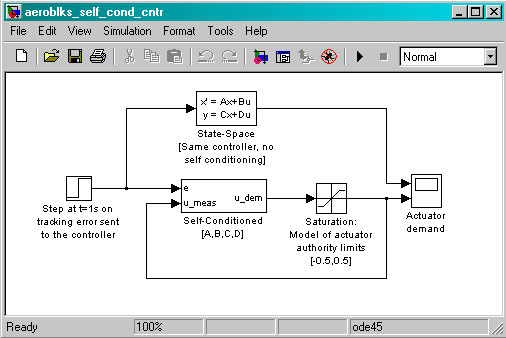
This Simulink model shows a state-space controller implemented in both self-conditioned and standard state-space forms. The actuator authority limits of +/- 0.5 units are modeled by the saturation block.


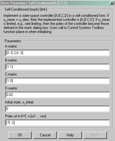
Notice that the A-matrix has a zero in the 1,1 element, indicating integral action.

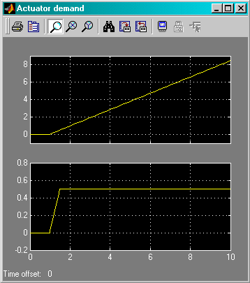
The top trace shows the conventional state-space implementation. The output of the controller winds up well past the actuator upper authority limit of +0.5. The lower trace shows that the self-conditioned form results in an actuator demand that tracks the upper authority limit, which means that when the sign of the control error, e, is reversed, the actuator demand responds immediately.
References
The algorithm used to determine the matrix H is defined in Kautsky, Nichols, and Van Dooren, "Robust Pole Assignment in Linear State Feedback," International Journal of Control, Vol. 41, No. 5, pages 1129-1155, 1985.
See Also
1D Self-Conditioned [A(v),B(v),C(v),D(v)]
2D Self-Conditioned [A(v),B(v),C(v),D(v)]
3D Self-Conditioned [A(v),B(v),C(v),D(v)]
 | Second Order Nonlinear Actuator | Temperature Conversion |  |