| Aerospace Blockset | |
Generate wind turbulence with the Dryden velocity spectra
Library
Description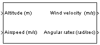
The Dryden Wind Turbulence Model block uses the Dryden spectral representation to add turbulence to the aerospace model by passing band-limited white noise through appropriate forming filters. This block implements the mathematical representation in the Military Specification MIL-F-8785C [1].
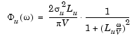
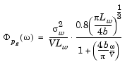
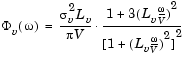
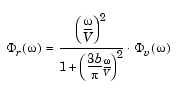
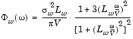
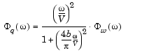
Turbulence can be considered as a stochastic process defined by velocity spectra. For an aircraft flying at a speed V through a "frozen" turbulence field with a spatial frequency of  radians per meter, the circular frequency
  is calculated by multiplying V by . The appropriate component spectra for the Dryden model of turbulence are shown here.
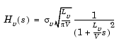
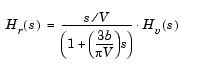
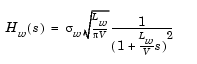
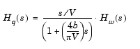
b is the aircraft wingspan,  are the turbulence scale lengths, and
  u, v, w are the turbulence intensities.
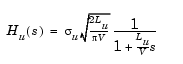
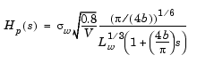
To generate a signal with the correct characteristics a unit variance band-limited white noise signal is passed through appropriate forming filters that are derived by taking the spectral square roots of the spectrum equations. The resulting transfer functions are shown here.
The turbulence scale lengths and intensities are functions of altitude, and there are two distinct regions.
Low-Altitude Model (Altitude < 1000 feet)
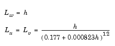
In [1] the turbulence scale lengths at low altitudes are as given below, where  is the altitude in feet.
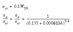
The turbulence intensities are given below, where  is the wind speed at 20 feet (6 m). Typically for "light" turbulence the wind speed at 20 feet is 15 knots, for "moderate" turbulence the wind speed is 30 knots, and for "severe" turbulence the wind speed is 45 knots.
Medium/High Altitudes (Altitude > 2000 feet)
For medium to high altitudes the turbulence scale lengths and intensities are based on the assumption that the turbulence is isotropic. In reference [1] the scale lengths are as given below:
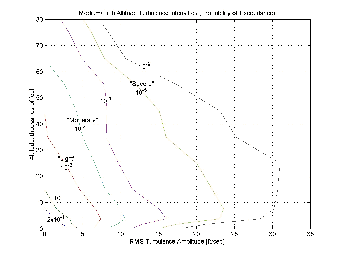
The turbulence intensities are determined from a lookup table that gives the turbulence intensity as a function of altitude and the probability of the turbulence intensity's being exceeded.
At altitudes between 1000 feet and 2000 feet, the turbulence scale lengths and intensities are determined by interpolating between the value from the low- altitude model at 1000 feet and the value from the high-altitude model at 2000 feet.
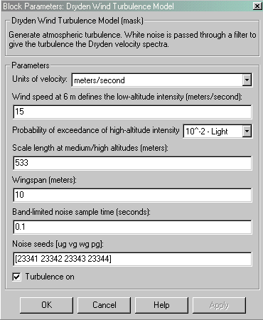
Dialog Box
| Wind Velocity |
Altitude |
Air Speed |
|
Meters/second |
Meters/second |
Meters |
Meters/second |
Feet/second |
Feet/second |
Feet |
Feet/second |
Knots |
Knots |
Feet |
Knots |
Inputs and Outputs
The first input is altitude, in units selected.
The second input is aircraft speed, in units selected.
The first output is a three-element signal containing the turbulence velocities, in the selected units.
The second output is a three-element signal containing the turbulence angular rates, in radians per second.
Examples
See the aeroblk_HL20.mdl example included with the blockset.
References
Military Specification MIL-F-8785C, 5th November, 1980.
See Also
Discrete Wind Gust Model
| | Discrete Wind Gust Model | Euler Angles to Direction Cosine Matrix | |