| Aerospace Blockset | |
Modeling the Homing Guidance Loop
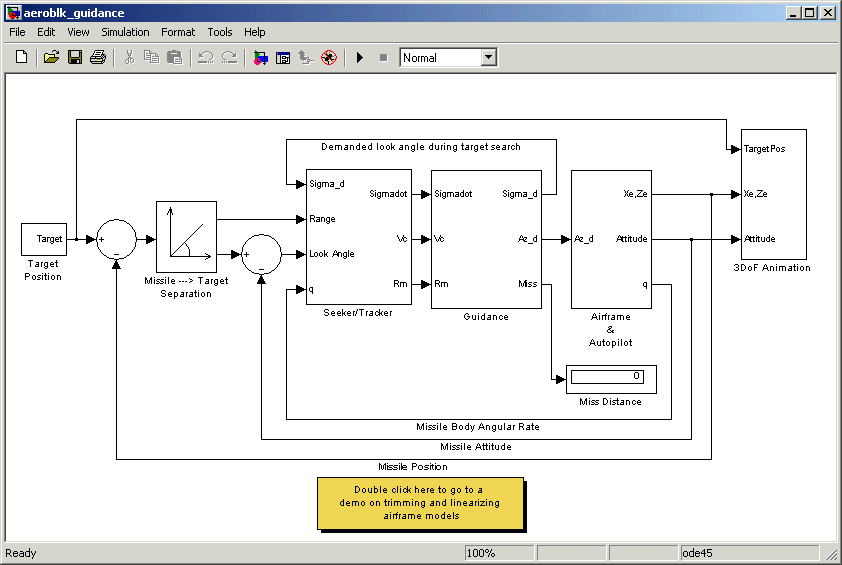
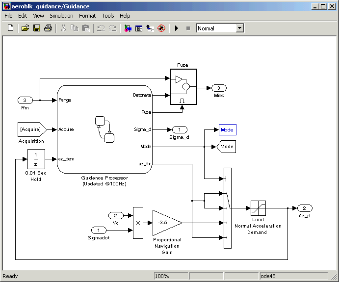
The complete homing guidance loop consists of these two subsystems:
The autopilot is now part of an inner loop within the overall homing guidance system. See Reference [4] for information on different types of guidance systems and on the analysis techniques that are used to quantify guidance loop performance.
Guidance Subsystem
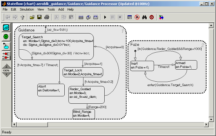
The Guidance subsystem performs an initial search to locate the target's position, and then generates demands during closed-loop tracking. A Stateflow model is used to control the transfer between the different modes of these operations. Stateflow is the ideal tool for rapidly defining all the operational modes, both during normal operation and during unusual situations.
Guidance Processor Statechart
Mode switching is triggered by events generated in Simulink or in the Stateflow chart. The variable Mode, which is passed out to Simulink, is used to control the Simulink model's behavior and to determine the response of the Simulink model. For example, the Guidance Processor state chart, which is part of the Guidance subsystem, shows the actions the system takes in response to either a loss of lock on the target or a failure to acquire the target's position during the target search.
During the target search, this Stateflow state chart controls the tracker directly by sending demands to the seeker gimbals (Sigma_d). Target acquisition is flagged by the tracker once the target lies within the beam width of the seeker (Acquire) and, after a short delay, closed loop guidance starts.
Proportional Navigation Guidance Measurements
Once the seeker has acquired the target a Proportional Navigation Guidance (PNG) law is used to guide the missile until impact. This form of guidance law has been used in guided missiles since the 1950s, and can be applied to radar-, infrared-, or television-guided missiles. The navigation law requires measurements of the closing velocity between the missile and target, which for a radar-guided missile can be obtained using a Doppler tracking device, and an estimate for the rate of change of the inertial sight line angle.
Proportional Navigation Guidance Measurements
az_dem =  Vc
Vc , the demanded normal acceleration.
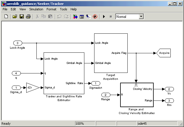
Seeker/Tracker Subsystem
The Seeker/Tracker subsystem controls the seeker gimbals to keep the seeker dish aligned with the target, and it provides the guidance law with an estimate of the sight line rate.
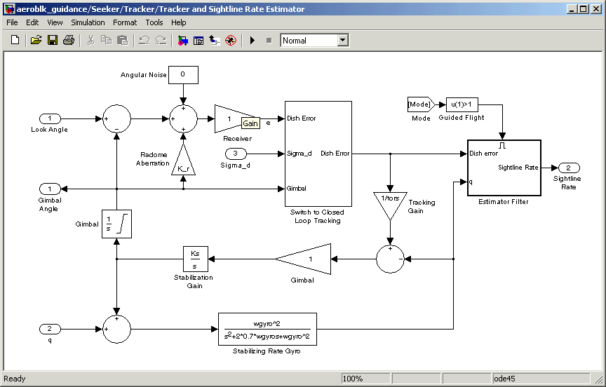
Tracker and Sightline Rate Estimator
The Tracker and Sightline Rate Estimator, which is the most interesting subsystem of the Seeker/Tracker subsystem because of its complex error modeling, is shown below. It contains a number of feedback loops, estimated parameters, and parasitic effects for the homing guidance. The tracker loop time constant tors is set to 0.05 seconds, which is a compromise between maximizing speed of response and keeping the noise transmission to within acceptable levels. The stabilization loop compensates for body rotation rates, and the gain Ks, which is the loop crossover frequency, is set as high as possible subject to the limitations of the bandwidth of the stabilizing rate gyro. The sight line rate estimate is a filtered value of the sum of the rate of change of the dish angle measured by the stabilizing rate gyro and an estimated value for the rate of change of the angular tracking error (e) measured by the receiver. In this demonstration the bandwidth of the estimator filter is set to half that of the bandwidth of the autopilot.
Radome aberration is also modeled by the Tracker and Sightline Rate Estimator subsystem. Radome aberration is a parasitic feedback effect that is commonly modeled in radar-guided missile designs. This effect occurs because the shape of the protective covering over the seeker distorts the returning signal, and then gives a false reading of the look angle to the target. Generally the amount of distortion is a nonlinear function of the current gimbal angle, but a commonly used approximation is to assume a linear relationship between the gimbal angle and the magnitude of the distortion. Other parasitic effects, such as sensitivity to normal acceleration in the rate gyros, are also often modeled to test the robustness of the target tracker and estimator filters.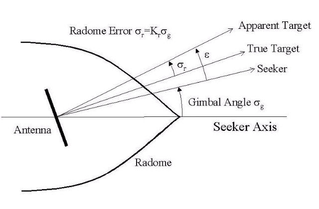
| | Modeling a Classical Three-Loop Autopilot | Simulating the Missile Guidance System | |
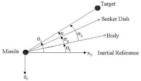
 b is body attitude.
 is sight line rate.
 g is gimbal angle.