| Aerospace Blockset |
  |
Modeling with the Aerospace Blockset
If you have never used Simulink before, take some time to get acquainted with its features.
Begin by learning the two basic stages in model construction, discussed in the following sections:
Model Definition
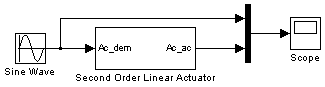
Simulink is a software package for modeling, simulating, and analyzing dynamic systems. Try building a simple model that drives an actuator with a sine wave and displays the actuator's position superimposed on the sine wave.
Note
If you prefer to open the complete model shown below instead of building it, type aeroblktutorial at the MATLAB command line.
|
Following are the procedures for defining a model on Windows and UNIX platforms.
Defining a Model on Windows Platforms
- Start Simulink.
- Click the
 button in the MATLAB toolbar or enter
 simulink in the MATLAB Command Window. The Library Browser appears.
- Open a new model.
- Select New -> Model from the File menu in the Library Browser. A new model window appears on your screen.
Alternate methods for creating a new model are by selecting New from the File menu in the Simulink model or by using the key sequence Ctrl+N.
- Add a Sine Wave block to the model.
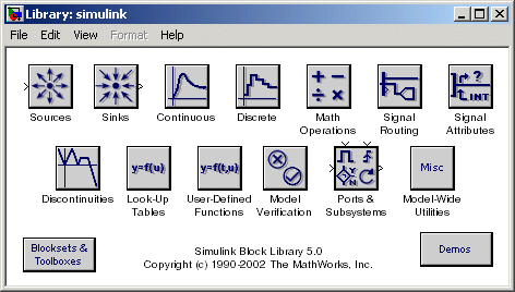
- Click Sources in the Library Browser to view the blocks in the Simulink
Sources library.
- Drag the Sine Wave block from the Sources library into the new model
window.
- Add a Second Order Linear Actuator block to the model.
- Click the
 symbol next to Aerospace Blockset in the Library Browser
to expand the hierarchical list of the aerospace blocks.
symbol next to Aerospace Blockset in the Library Browser
to expand the hierarchical list of the aerospace blocks.
- In the expanded list, click Actuators to view the blocks in the Actuator
library.
- Drag the Second Order Linear Actuator block into the model window.
- Add a Mux block to the model.
- Click Signal Routing in the Library Browser to view the blocks in the
Simulink Signals & Systems library.
- Drag the Mux block from the Signal Routing library into the model
window.
- Add a Scope block to the model.
- Click Sinks in the Library Browser to view the blocks in the Simulink
Sinks library.
- Drag the Scope block from the Sinks library into the model window.
- Resize the Mux block in the model.
- Click the Mux block to select the block.
- Hold down the mouse button and drag a corner of the Mux block to
change the size of the block.
- Connect the blocks.
- Position the pointer near the output port of the Sine Wave block. Hold
down the mouse button and drag the line that appears until it touches the
input port of the Second Order Linear Actuator block. Release the mouse
button.
- Using the same technique, connect the output of the Second Order Linear
Actuator block to the second input port of the Mux block.
- Using the same technique, connect the output of the Mux block to the
input port of the Scope block.
- Position the pointer near the first input port of the Mux block. Hold down
the mouse button and drag the line that appears over the line from the
output port of the Sine Wave block until double crosshairs appear.
Release the mouse button. The lines are connected when a knot is present
at their intersection.
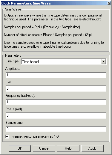
- Set the block parameters.
- Double-click the Sine Wave block. The dialog box that appears allows you
to set the block's parameters. Parameters are defining values that tell the
block how to operate.
- Click OK.
- Double-click the Second Order Linear Actuator block.
-
For this example, the actuator has the default natural frequency of 150 rad/sec, a damping ratio of 0.7, and an initial condition of 0 radians specified by the Natural frequency, Damping ratio, and Initial condition parameters.
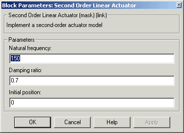
- Click OK.
You can now move on to the model simulation phase. See Model Simulation.
Defining a Model on UNIX Platforms
- Start Simulink.
- Enter
simulink in the MATLAB Command Window. The Simulink Library window appears.
- Open a new model.
- Select New -> Model from the File menu in the Simulink Library window. A new model window appears on your screen.
Alternate methods for creating a new model are by selecting New from the File menu in the Simulink model or by using the key sequence Ctrl+N.
- Add a Sine Wave block to the model.
- Double-click Sources in the Simulink Library window to view the blocks
in the Simulink Sources library.
- Drag the Sine Wave block from the Sources library into the new model
window.
- Add a Second Order Linear Actuator block to the model.
- Double-click Blocksets & Toolboxes in the Simulink Library window.
This opens the Blocksets and Toolboxes Library window.
- Double-click Aerospace Blockset in the Blocksets and Toolboxes Library
window. This opens the Aerospace Blockset block libraries.
- In the Aerospace Blockset block libraries, click Actuators to view the
blocks in the Actuator library.
- Drag the Second Order Linear Actuator block into the model window.
- Add a Mux block to the model.
- Double-click Signal Routing in the Simulink Library to view the Signal
Routing blocks.
- Drag the Mux block from the Signal Routing library into the model
window.
- Add a Scope block to the model.
- Double-click Sinks in the Simulink Library window to view the blocks in
the Simulink Sinks library.
- Drag the Scope block from the Sinks library into the model window.
- Resize the Mux block in the model.
- Click the Mux block to select the block.
- Hold down the mouse button and drag a corner of the Mux block to
change the size of the block.
- Connect the blocks.
- Position the pointer near the output port of the Sine Wave block. Hold
down the mouse button and drag the line that appears until it touches the
input port of the Second Order Linear Actuator block. Release the mouse
button.
- Using the same technique, connect the output of the Second Order Linear
Actuator block to the second input port of the Mux block.
- Using the same technique, connect the output of the Mux block to the
input port of the Scope block.
- Position the pointer near the first input port of the Mux block. Hold down
the mouse button and drag the line that appears over the line from the
output port of the Sine Wave block until double crosshairs appear.
Release the mouse button. The lines are connected when a knot is present
at their intersection.
- Set the block parameters.
- Double-click the Sine Wave block. The dialog box that appears allows you
to set the block's parameters. Parameters are defining values that tell the
block how to operate.
- Click OK.
- Double-click the Second Order Linear Actuator block.
-
For this example, the actuator has the default natural frequency of 150 rad/sec, a damping ratio of 0.7, and an initial condition of 0 radians specified by the Natural frequency, Damping ratio, and Initial condition parameters.
- Click OK.
You can now move on to the model simulation phase. See Model Simulation.
| | Opening the Aerospace Blockset on UNIX Platforms | | Model Simulation | |