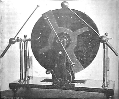
In 1903, the instrument builder Alfred
Wehrsen patented a disk for influence machines
that had internal sectors accessed trough buttons in the face of the
disk. This disk was used in the machines described by Wommelsdorf in
1908 [p77], and built by Wehrsen. Most of
the machines described there
were Voss-type
machines with just one rotating disk, but machines with two disks
turning in opposite directions were also mentioned.
Disks with embedded sectors, built with a different technique, were
used also previously in other machines, as the ones described by Pidgeon [p53][p54].
In 2008 I decided to build one of these machines. I had before made machines having disks with embedded sectors, one being a Wehrsen machine, and another a Wommelsdorf condenser machine. For these machines I made the disks by stacking three acrylic disks with sectors of adhesive aluminum foil mounted between them, and sealing the assembly with hot glue in a kitchen oven. Access to the sectors was trough buttons in front of the disk, in the case of the Wehrsen machine, or trough the edge, in the case of the consenser machine. The result was good, but the use of intense heat was not good for the acrylic disks, that were somewhat deformed, I started the construction of a large Wehrsen machine, but could not make the disks using this technique, and the machine ended with a Wimshurst disk.
For this new machine I decided to try a different construction method, using adhesive plastic foil for insulation. The construction of the disks would be quite simple in this way, although with some risk of failure due to unavoidable air spaces around the sectors, and less insulation.
In the first disks tried the sectors had 8 cm of length and width 10 times larger than the separation, considering 32 sectors. The disks had a diameter of 32 cm, made with black acrylic. In initial tests with just the first layer of sectors installed, the machine produced a quite high output current, reaching almost the current that would be expected from the final machine (50 µA at 4 turns/second in the crank). A possible consequence of the large sectors. The spark length was consistent with the dimensions of the disks and sectors, 8 cm. The machine was left in this state for several months.
The construction was continued in April 2009. The disks were completed by first covering the disks and the first layer of sectors with two layers of transparent adhesive plastic foil ("Contact"), with maximum care to avoid bubbles. The foil was first cut in disks with 1 cm margin around the acrylic disks, and applied starting from one side, detaching the back cover a few mm at a time, while pressing the exposed adhesive foil against the acrylic disks with a paper towel, from the center to the borders. Everything was cleaned with alcohol and dried before the assembly. Excess foil was then cut out with a sharp knife. The second layer of sectors was then applied, and the assembly covered by two more layers of plastic foil, one transparent and one black. A series of slits was cut at the positions of the buttons, with a soldering iron with a sharp tip melting the plastic but not damaging the aluminum sectors. Small slips of thick aluminum foil were inserted on the slits, after opening some space under one side of them with a small screwdriver, and after this the foil was firmly pressed in place again. The buttons, aluminum disks with 9mm of diameter, were then glued with contact glue over the slits, making contact with the foil slips and so with the internal sectors. Good contacts were verified by measuring the capacitance between the buttons and a metal plate inserted below the disks. The insulation was verified by charging an electrometer in contact with a button, and verifying the effect of touching the buttons close the one in test. The insulation was found good, but a significant capacitance between adjacent sectors was noticed. The disks were fixed to the bosses with three flat head screws, with a layer of flexible material between the disks and the bosses.
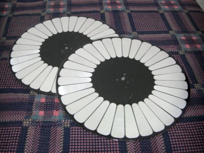
Disks with single layer of 24 sectors.
In 2008 I decided to build one of these machines. I had before made machines having disks with embedded sectors, one being a Wehrsen machine, and another a Wommelsdorf condenser machine. For these machines I made the disks by stacking three acrylic disks with sectors of adhesive aluminum foil mounted between them, and sealing the assembly with hot glue in a kitchen oven. Access to the sectors was trough buttons in front of the disk, in the case of the Wehrsen machine, or trough the edge, in the case of the consenser machine. The result was good, but the use of intense heat was not good for the acrylic disks, that were somewhat deformed, I started the construction of a large Wehrsen machine, but could not make the disks using this technique, and the machine ended with a Wimshurst disk.
For this new machine I decided to try a different construction method, using adhesive plastic foil for insulation. The construction of the disks would be quite simple in this way, although with some risk of failure due to unavoidable air spaces around the sectors, and less insulation.
The structure of the machine is
different from the usual. I made two upright supports in hard wood,
similar
to the ones that I had already used in other machines, with a tapered
vertical support and a horizontal cylinder at the top. I mounted the
frontal disk fixed trough a wood cylinder with a set screw on a 6 mm
steel
axle that runs on two ball bearings at the tops of the vertical
supports, and the back disk on a boss that rotates on two ball
bearings around the axle. The pulleys driving the disks were mounted
on both sides of the back upright support, one made in the boss that
supports the back disk, and the other fixed to the axle, driving the
front disk. The usual crossed cords make the disks turn in opposite
directions, driven by a set of two
larger pulleys mounted on a separate structure, also with ball
bearings.
The driving cords were made with medical tubes. Each turn on the crank
turns the disks 4 times. This structure allows easy variation of the
spacing between the disks,
since in these machines there is an optimum value for this distance.
The neutralizers are mounted on brass rings in the upright supports,
with the distance from the disks adjustable by sliding horizontal bars.
The brushes were made with three sections of embroidering line wrapped
with thin nickel-chrome wire
inserted in holes at the end of the sliding bars. This technique
results in brushes that don't break easily when touching the buttons in
the disks.
The charge collectors are mounted in brass bars close to the edge of
the disks, and are simply thin wire brushes that don't touch the disks.
Plastic balls were used in the joints and ends for insulation. The
collectors can be rotated, so they pick charge at the horizontal
diameter of the disks, or a few cm above or below. This allows
experiments to see how to maximize the output current and the output
voltage. The two
horizontal
conductors are supported by wood balls over PVC tube columns, sealed
with nylon plugs and hot glue. The spark terminals are also mounted on
wood balls, and can rotate at the ends of the horizontal conductors.
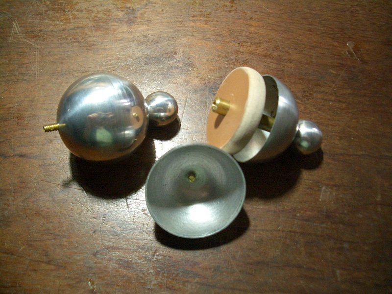
The handles are thin PVC tubes, and the spark
balls are hollow aluminum
balls made by metal spinning with smaller solid balls attached to them.
Two Leyden jars made from plastic cups complete the machine. The outer
plates of the jars are interconnected at an adjustable spark gap in
front of the machine. High-voltage pulses and sparks can be obtained
there if the gap is open, when sparks occur at the main terminals.
The machine was mounted on a plywood base, leveled, polished, and painted in black
The machine was mounted on a plywood base, leveled, polished, and painted in black
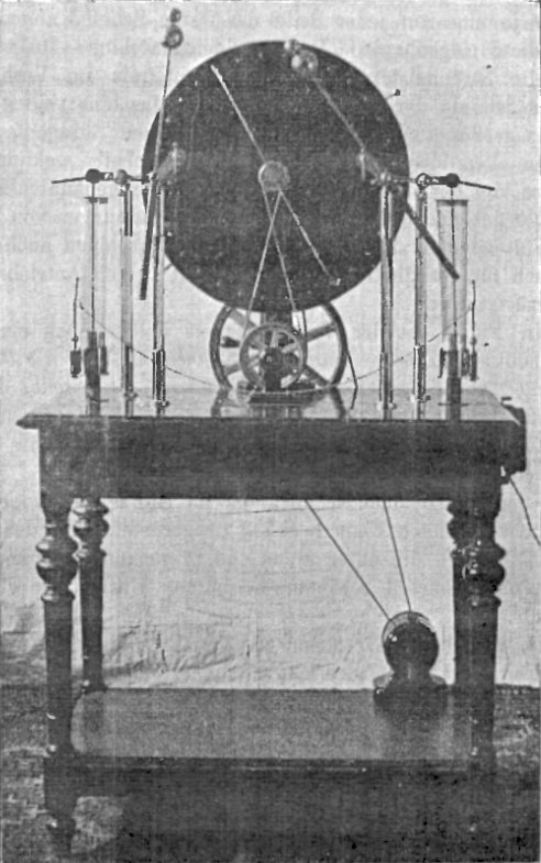
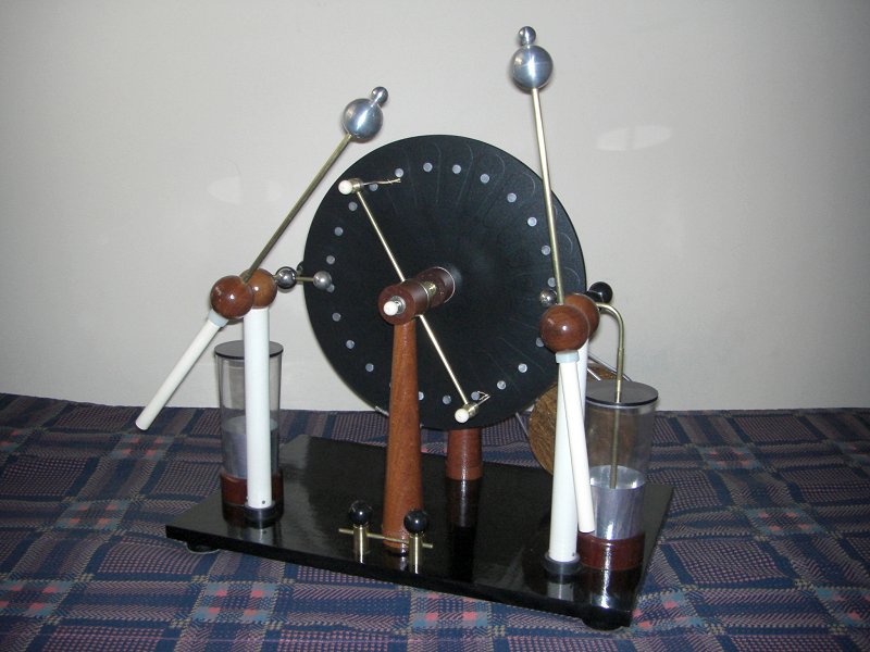
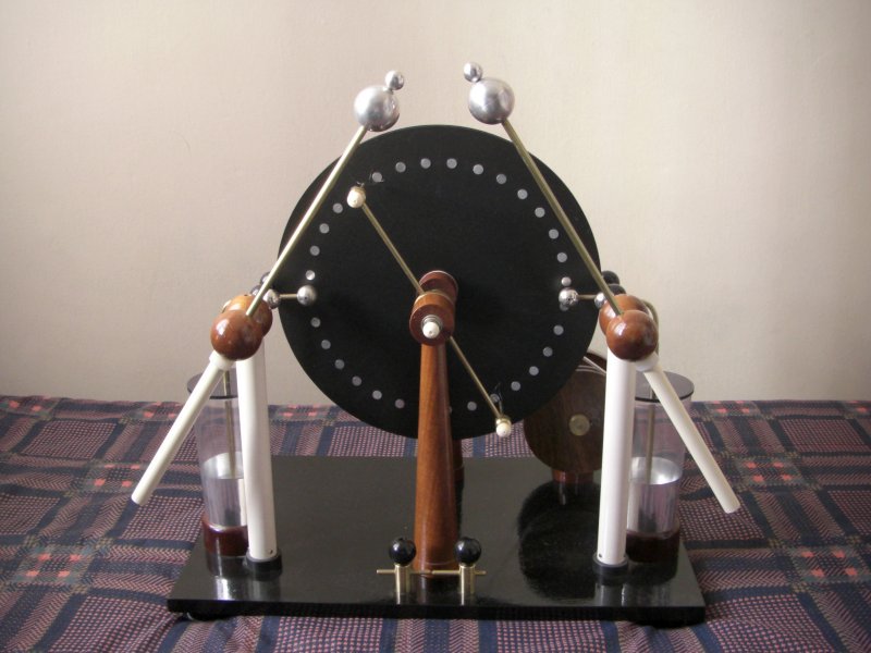
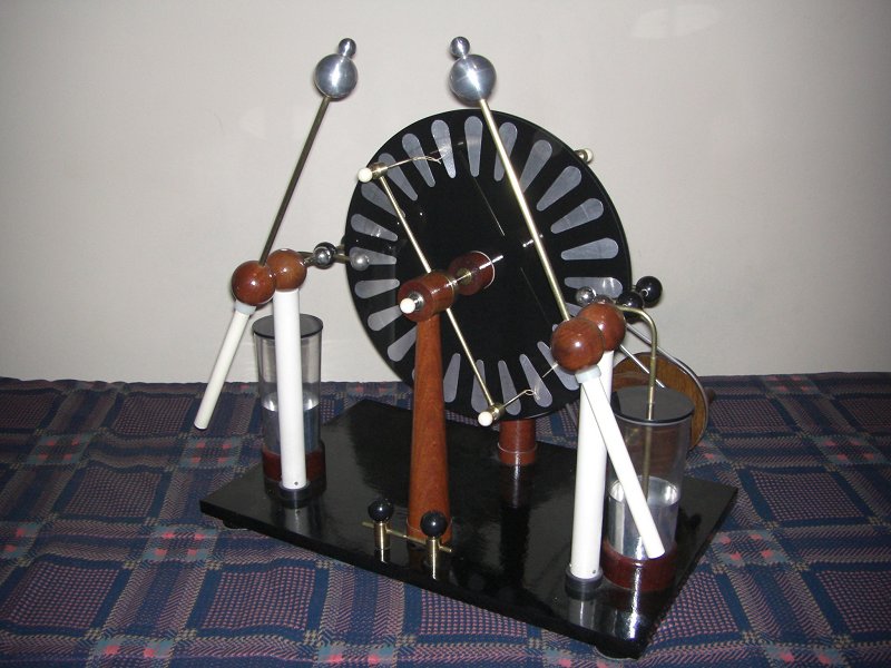
Front view of the machine with the 24
sectors disks. The frontal disk can be moved, varying its distance to
the back disk.
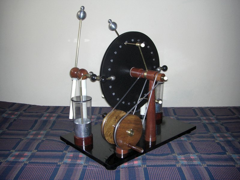
Another view, showing the pulley
system
and assembly of the back disk.
In the first disks tried the sectors had 8 cm of length and width 10 times larger than the separation, considering 32 sectors. The disks had a diameter of 32 cm, made with black acrylic. In initial tests with just the first layer of sectors installed, the machine produced a quite high output current, reaching almost the current that would be expected from the final machine (50 µA at 4 turns/second in the crank). A possible consequence of the large sectors. The spark length was consistent with the dimensions of the disks and sectors, 8 cm. The machine was left in this state for several months.
The construction was continued in April 2009. The disks were completed by first covering the disks and the first layer of sectors with two layers of transparent adhesive plastic foil ("Contact"), with maximum care to avoid bubbles. The foil was first cut in disks with 1 cm margin around the acrylic disks, and applied starting from one side, detaching the back cover a few mm at a time, while pressing the exposed adhesive foil against the acrylic disks with a paper towel, from the center to the borders. Everything was cleaned with alcohol and dried before the assembly. Excess foil was then cut out with a sharp knife. The second layer of sectors was then applied, and the assembly covered by two more layers of plastic foil, one transparent and one black. A series of slits was cut at the positions of the buttons, with a soldering iron with a sharp tip melting the plastic but not damaging the aluminum sectors. Small slips of thick aluminum foil were inserted on the slits, after opening some space under one side of them with a small screwdriver, and after this the foil was firmly pressed in place again. The buttons, aluminum disks with 9mm of diameter, were then glued with contact glue over the slits, making contact with the foil slips and so with the internal sectors. Good contacts were verified by measuring the capacitance between the buttons and a metal plate inserted below the disks. The insulation was verified by charging an electrometer in contact with a button, and verifying the effect of touching the buttons close the one in test. The insulation was found good, but a significant capacitance between adjacent sectors was noticed. The disks were fixed to the bosses with three flat head screws, with a layer of flexible material between the disks and the bosses.
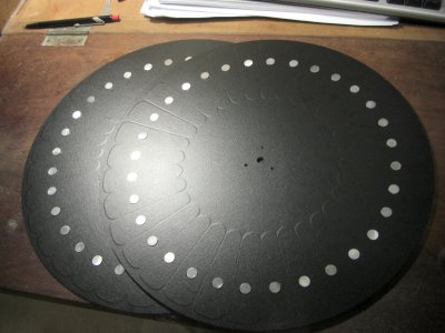
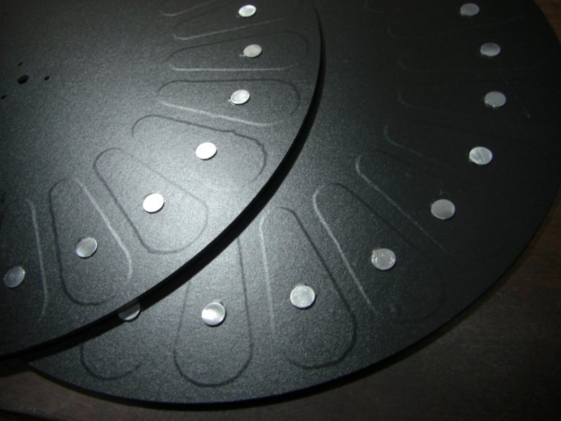
Disk assembly, with two layers of
sectors.
The disks with two layers of sectors
and the final assembly with cover and access buttons.
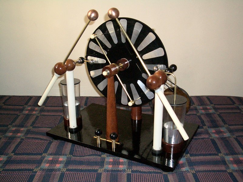
Machine with the disks with 32
intercalated embedded
sectors.
To verify if the problem was the excessive capacitance between adjacent sectors, a new set of disks was made, with 24 sectors in a single layer, with lateral insulation provided by larger separation between adjacent sectors, with the same two layers of plastic foil used in the other disks covering the sectors. Contact buttons were then added in the same way. The sectors were made with the average width two times larger than the spacing, with 7 cm of length. The machine was tested before the installation of the insulating cover, and it easily sparked trough the sectors and neutralizers when sparks longer that 7 cm were attempted.
In initial tests the observed
performance was poor. The machine could produce a quite high current
(50 µA at 4 turns/second at the crank) easily, but the spark
length was not exceeding 3 cm. At this
point, where the voltage ceases to increase, by looking at the machine
operating in the dark it was possible to see sparking between the disks
and corona over the disks, at the lines where adjacent sectors meet. It
was possible to obtain some improvement by increasing the distance
between the disks, but this reduces the current and turns the machine
more difficult to start. About 1 cm more of spark length was obtained
with this.
To verify if the problem was the excessive capacitance between adjacent sectors, a new set of disks was made, with 24 sectors in a single layer, with lateral insulation provided by larger separation between adjacent sectors, with the same two layers of plastic foil used in the other disks covering the sectors. Contact buttons were then added in the same way. The sectors were made with the average width two times larger than the spacing, with 7 cm of length. The machine was tested before the installation of the insulating cover, and it easily sparked trough the sectors and neutralizers when sparks longer that 7 cm were attempted.
Disk assembly with a single layer of
sectors.
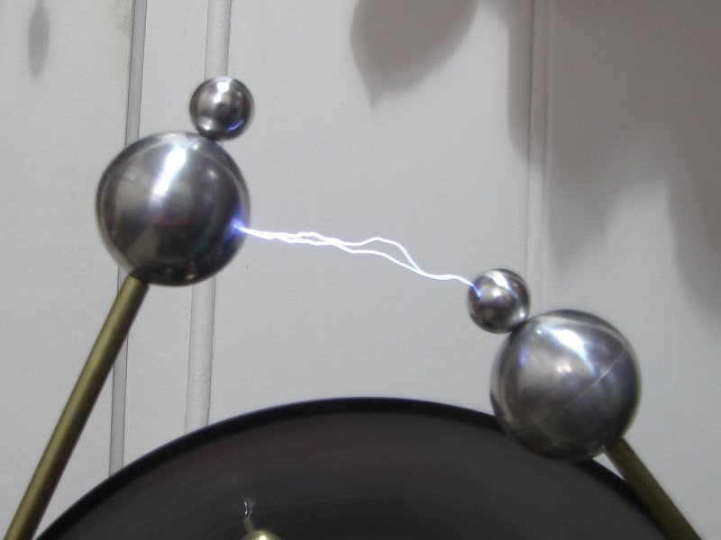
With the complete disks the machine
worked
very well, producing sparks with up to 13 cm even with more than 80% of
humidity in the air. The limit is in the terminals, that start to
produce "failed sparks" at this point. The current (measured between
one terminal and the
neutralizers) was measured as 10 µA for each turn per second of
the crank. A bit more than the 7 µA expected for open sectors of
this size. The disks were not very
uniform in thickness, and had to be balanced by
gluing small lead cubes at the lighter edge until satisfactory balance
was reached. This introduces some loss and is quite ugly, but works.
A video of the machine in operation:
Operation with conventional disks
For a better evaluation if it is really worthwile to build the disks in this way, I made another set of disks, with 24 open sectors, designed to produce more than 13 cm of spark length, with a reasonable current. I designed the sectors with a ratio of average sector width to sector spacing of 0.76, 0.5 cm outer margin and 6 cm of length. The WMD program predicts 14.8 cm of spark length and 4 µA of current at 1 turn/second in the crank. These predictions are approximate, and the predicted current is usually below by a good margin if the sectors are small. The machine worked very well, producing 13 cm sparks easily, and 7 µA at 1 turn/second in the crank. The spark length is being evidently limited by the shape of the terminals, not by the disks. It appears also insensitive to humidity, at least in the initial tests with the disks very clean. The machine starts more easily than the machine with closed sectors, as it is not necessary to adjust the neutralizer brushes so they touch the buttons. The disadvantages are a smaller output current, because the sectors must be small to allow long sparks without sparking trough the sectors, and a significantly higher production of ozone. The machine appears to be somewhat harder to turn too, a sign of inefficiency, but this can be improved by adjusting the separation of the disks.
A video:
A video of the machine in operation:
Operation with conventional disks
Machine with conventional 24 sectors
disks
For a better evaluation if it is really worthwile to build the disks in this way, I made another set of disks, with 24 open sectors, designed to produce more than 13 cm of spark length, with a reasonable current. I designed the sectors with a ratio of average sector width to sector spacing of 0.76, 0.5 cm outer margin and 6 cm of length. The WMD program predicts 14.8 cm of spark length and 4 µA of current at 1 turn/second in the crank. These predictions are approximate, and the predicted current is usually below by a good margin if the sectors are small. The machine worked very well, producing 13 cm sparks easily, and 7 µA at 1 turn/second in the crank. The spark length is being evidently limited by the shape of the terminals, not by the disks. It appears also insensitive to humidity, at least in the initial tests with the disks very clean. The machine starts more easily than the machine with closed sectors, as it is not necessary to adjust the neutralizer brushes so they touch the buttons. The disadvantages are a smaller output current, because the sectors must be small to allow long sparks without sparking trough the sectors, and a significantly higher production of ozone. The machine appears to be somewhat harder to turn too, a sign of inefficiency, but this can be improved by adjusting the separation of the disks.
A video: