A 6th-order
Tesla Magnifier
(or a transformer-coupled triple
resonance network with distributed load capacitance)
 By April 2003 I started
experiments with a 6th-order Tesla magnifier, in an attempt to
verify if the design method developed for triple resonance networks can be also
useful for an application intended for the production of sparks
and streamers, a variation of the classical Tesla
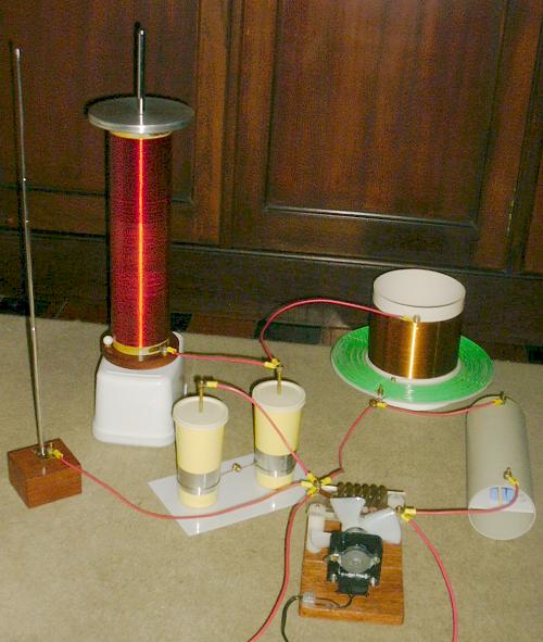
coil. The 6th-order Tesla magnifier consists in a
low-impedance primary LC tank circuit L1-C1
magnetically coupled to a medium-impedance tank L2-C2,
used as a "driver" for a high-impedance resonator
formed by the third coil L3 and its
distributed load capacitance C3. The device
is powered by a neon sign transformer (NST) that has a spark gap
across its output. The NST charges C1 to the
firing voltage of the gap, and while the gap conducts the circuit
executes a transient involving symultaneous oscillations at three
frequencies that, with proper design, ideally transfers all the
energy initially stored in C1 to the
distributed capacitance C3, producing pulses
of very high voltage because C3<<C1.
I had previously experimented with a directly
coupled version of this circuit, that resulted in just
reasonable performance. Directly coupled multiple
resonance networks have the voltage gain associated with the
number of oscillation cycles required for complete energy
transfer, and so are quite inflexible. With the use of magnetic
coupling, it's possible to remove this dependency, and so, in
principle, to achieve better efficiency by reducing the energy
transfer time.
By April 2003 I started
experiments with a 6th-order Tesla magnifier, in an attempt to
verify if the design method developed for triple resonance networks can be also
useful for an application intended for the production of sparks
and streamers, a variation of the classical Tesla
coil. The 6th-order Tesla magnifier consists in a
low-impedance primary LC tank circuit L1-C1
magnetically coupled to a medium-impedance tank L2-C2,
used as a "driver" for a high-impedance resonator
formed by the third coil L3 and its
distributed load capacitance C3. The device
is powered by a neon sign transformer (NST) that has a spark gap
across its output. The NST charges C1 to the
firing voltage of the gap, and while the gap conducts the circuit
executes a transient involving symultaneous oscillations at three
frequencies that, with proper design, ideally transfers all the
energy initially stored in C1 to the
distributed capacitance C3, producing pulses
of very high voltage because C3<<C1.
I had previously experimented with a directly
coupled version of this circuit, that resulted in just
reasonable performance. Directly coupled multiple
resonance networks have the voltage gain associated with the
number of oscillation cycles required for complete energy
transfer, and so are quite inflexible. With the use of magnetic
coupling, it's possible to remove this dependency, and so, in
principle, to achieve better efficiency by reducing the energy
transfer time.
My system was designed for operation in mode 3:4:5, what means
that the energy transfer transient has oscillations at three
frequencies that are in this ratio. I used the same C1,
L3, and C3 that I had
prepared for previous experiments. With
the help of the design formulas shown here,
the remaining elements L1, L2,
C2, and the coupling coefficient k12
can be calculated. The program mrn6 can
make the calculations and plot the expected ideal
waveforms. The result was:
C1 = 5.08 nF
L1 = 62.02 µH
C2 = 79.64 pF
L2 = 3.948 mH
C3 = 9.8 pF
L3 = 28.2 mH
k12 = 0.3504
Voltage gain: 22.77
Energy transfer time: 6.606 µs
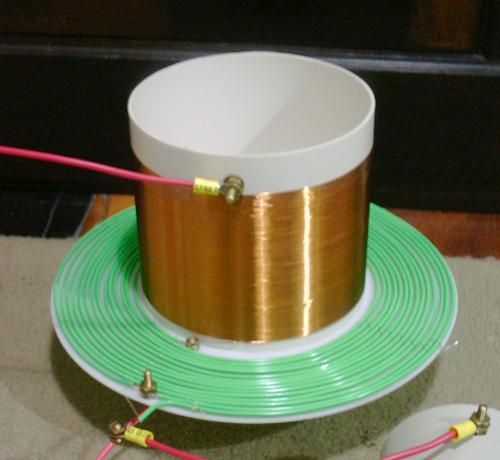
The driver transformer was designed
with the help of the program Inca, that
can calculate inductances and mutual inductances with great
precision. L1 was made as a flat coil and L2
as a short solenoidal coil. This configuration produces the
required quite high coupling, but doesn't present serious
insulation problems.
Primary: 14 turns; internal radius = 8 cm; external radius =
12 cm; wire diameter = 1 mm (#18).
L1= 0.06207 mH
Secondary: 176 turns; length = 10.2 cm; radius = 7.4 cm; wire
diameter = 0.51 mm (#24); height above L1 =
7.5 mm
L2= 3.949 mH
Mutual Inductance M = 0.1734 mH
Coupling coefficient k12 = 0.3501
The capacitance C2 consists in the
distributed capacitance present in the interconnection between L2
and L3 and in a lumped capacitor that
completes it to the required value. The distributed capacitance
can be estimated as somewhat larger than the sum of the Medhurst
capacitances of L2 (7.1 pF) and L3
(5.6 pF), for the configuration used. To determine how large the
lumped capacitor must be, I made a low-power test using a
low-impedance square-wave generator, set to low frequency, in
place of the spark gap, and used a variable capacitor as C2.
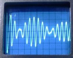
The waveforms observed at the transitions of the square wave are
similar to the ones that would be observed starting with a
charged C1. The waveforms below were obtained
with a lumped C2 = 62 pF, and the antenna at
the top load at its minimum length. They correspond closely to
the ideal waveforms.
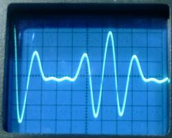
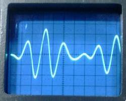
VL1, VL2,
and VL3. 2 µs/div.
The energy transfer in 6.6 µs can be observed.
The three resonance frequencies were measured as 232, 307, and
385 kHz. The ideal values would be 228, 304, and 380 kHz. The
obtained precision was quite good, with errors of 1.8%, -1%, and
-1.3% in the frequencies.
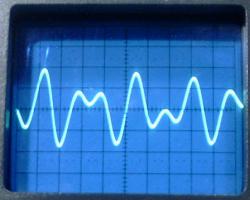
Without a lumped C2, the
system falls close to a higher mode, that uses the remaining
distributed C2 = 17.64 pF. The mode 6:7:14
would result in L1= 61.77 µH, C2=
24.63 pF, L2= 3.819 mH, and k12=
0.3453, for the same other elements. The energy transfer for this
mode occurs in 3.5 cycles, close to the observed. The input and
output voltages are similar to what occurs in a two coils system
operating in mode 6:7, a mode that I could obtain with my Tesla
coil only when I connected it as an Oudin coil. The magnifier
configuration results in faster energy transfer even when a
lumped C2 is not used.
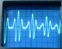
VL1 with a lumped C2
and without. 5 µs/div.
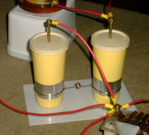
The construction of a suitable C2 is not
easy. Simulations show that C2 has to sustain
26 kV for a gap voltage of 5 kV, during the energy transfer, and
somewhat more after the gap quenching. What I tried initially was
to make a pair of Leyden jars using
plastic cups (polypropylene), each with 124 pF. My reasoning was
that with less voltage and more metal area in the capacitors, the
losses would be smaller. The performance of the system in a full
power test, however, was not as good as the performance of a
conventional Tesla coil with the same
elements. It was just a bit better than what I had obtained with
the directly coupled 6th-order system.
Without the lumped C2, the performance was
significantly better, close to the performance of my Tesla coil. C2 was
evidently consuming significant energy, with intense corona
around the edges of the plates, and becoming warm quickly. A
better approach would be to make a big "mmc" capacitor,
by connecting several medium-voltage commercial capacitors in
series (look here for a
2:3:4 magnifier made by Terry Fritz).
Another problem that could be causing the poor performance is
that with narrow "notches" in the primary waveforms,
the primary gap could not be "quenching" (ceasing to
conduct) when the energy transfer is complete, while this
continued to happen in the version with a distributed C2
only, that has more gradual "notches". Further tests
will reveal what is happening.
Still another possible cause of poor performance is that the
rms voltage at the output of a 6th-order system, for the same
peak output voltage, is smaller than the rms voltage in a
4th-order system. During the energy transfer, this is caused by
the "second order" notches that the 6th-order system
produces. Ignoring losses, in a 4th-order system, for all modes
the ratio between the rms value of the output voltage and the
peak voltage is 0.5 while the gap conducts. For a 6th-order
system it varies from 0.4375 for mode 1:2:3 to 0.4330 for high
modes (0.4341 for mode 3:4:5). After the quenching of the gap,
the oscillation of the energy in the 4th-order system formed by L2,
C2, L3, and C3
may also reduce the rms output voltage.
Spark pictures soon.
Programs that can design and simulate the behavior of this
system, and others, can be found here.
Extensive materials about Tesla coils can be found in the
archives of the Tesla list.
[1] See the papers about "multiple
resonance networks" here.
Warning:
This device is powered by a
power source that has enough voltage, and specially enough
current, to give a fatal shock. The NST, the terminals of C1,
L1,
C2,
L2,
and the spark gap must not be touched in any circunstance while
the system is energized. The high-voltage arcs are also not safe
to touch. They may cause burns, and the current is intense enough
to cause internal body damage.
Created: 11 May 2003 (optimized for 800x600).
Last update: 12 May 2003
Created and maintained by Antonio Carlos
M. de Queiroz
See also: Electrostatic Machines