 A machine that can be considered the first
symmetrical rotating electrostatic influence machine was described by Giuseppe Belli his book about electricity published in
1838 [60]. The basic idea of the machine appeared in a paper in 1831 [p61], with hints of it being first constructed by 1826. The same idea was rediscovered later by Varley,
in 1860, and by Lord Kelvin (William Thomsom), in 1867 [p92]. Kelvin
developed an electrostatic
machine to generate charge for electrifiying the ink in a telegraph
printer, and used a similar device based on the same idea in electrical
instruments to regenerate small charges, called the "replenisher".
A machine that can be considered the first
symmetrical rotating electrostatic influence machine was described by Giuseppe Belli his book about electricity published in
1838 [60]. The basic idea of the machine appeared in a paper in 1831 [p61], with hints of it being first constructed by 1826. The same idea was rediscovered later by Varley,
in 1860, and by Lord Kelvin (William Thomsom), in 1867 [p92]. Kelvin
developed an electrostatic
machine to generate charge for electrifiying the ink in a telegraph
printer, and used a similar device based on the same idea in electrical
instruments to regenerate small charges, called the "replenisher". 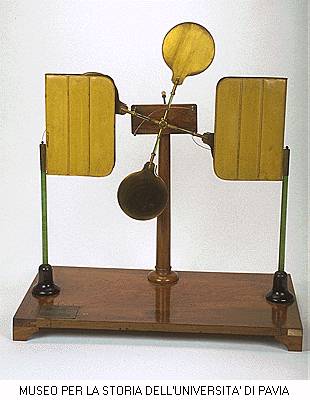
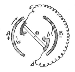
The schematic diagram at left shows the structure of the machine. Two curved metal plates P and Q are fixed to a rotating axle O by insulating rods. They rotate inside two larger curved metal plates A and B, also insulated. Springs a and b connect the rotating plates with the outer plates when they are at the horizontal diameter, and springs c and d short-circuit the rotating plates when they are about to leave the outer plates. if there is a charge imbalance between the outer plates, in the case with A being positive and B negative, when the rotating plates are as shown opposite charges are attracted to them. When they continue to rotate and touch the springs a and b, most of the charges in them are transferred to the outer plates by a Faraday ice pail effect, reinforcing the original charges. The cycle then repeats with opposite polarities in P and Q. If the capacitances between the inner plates and outer plates is dominant, each half cycle almost doubles the charges in A and B. In the usual application, one of the plates is connected to an insulated conductor where the voltage is to be kept at certain level. The device is turned manually to restore the charge when the voltage drops due to leakage. The other plate can be left floating, with the conductor cd grounded, or can be grounded, with the conductor cd left floating.
An interesting flat version of the device, at the University of Innsbruck Museum. Another machine, in a demonstration at the Deutsches Museum (from this site).
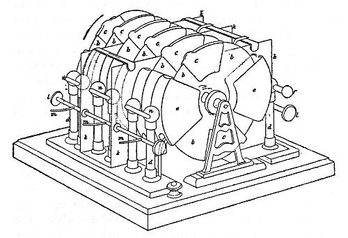
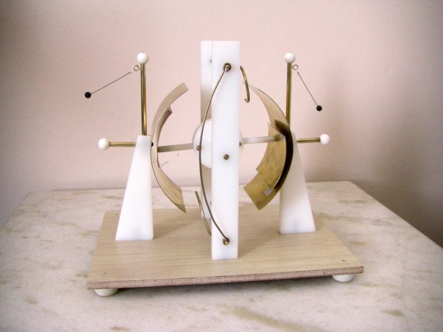
I build a crude version of this machine by 1973, the first electrostatic machine that I built, that worked quite well but was very small. Im January 2011 I built a larger machine, shown below.
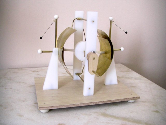
The machine, crank side.