The Bohnenberger machine
 This curious machine
[4] [p14] is
a "doubler", a primitive influence machine, proposed by
Bohnenberger in 1798, as a rotating implementation of Bennet's doubler (1787, used as an
electrometer and built in this way)). It
differs from the first rotating doubler, Nicholson's
doubler (1788), by rotating the pair of plates with the same
polarity instead of the single plate. This has the advantage of a
more balanced construction which rotates with less vibration, and
of just one rotating connection.
This curious machine
[4] [p14] is
a "doubler", a primitive influence machine, proposed by
Bohnenberger in 1798, as a rotating implementation of Bennet's doubler (1787, used as an
electrometer and built in this way)). It
differs from the first rotating doubler, Nicholson's
doubler (1788), by rotating the pair of plates with the same
polarity instead of the single plate. This has the advantage of a
more balanced construction which rotates with less vibration, and
of just one rotating connection.
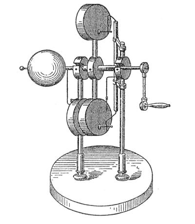
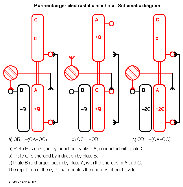
The machine is composed of two insulated thick disks of
conductive material that rotate in an horizontal spindle, turned
by a winch. These are the two fixed plates in Bennet's doubler.
Mounted in these disks are two metallic pins, at different
distances from the spindle. These pins, at the position shown in
the pictures, are short-circuited by a vertical insulated
conductor mounted in the machine's support. When the assembly is
rotated by 180 degrees, the disk with the pin closer to the
center is grounded by a contact, also mounted in the machine's
structure. Mounted in the support opposite to the side of the
crank, there is another insulated thick disk of conductive
material, that is equivalent to the moving plate of Bennet's
doubler. With the machine at the position shown, it is touched by
a grounded wire, that turns with the spindle. The large ball
shown in the old engraving replaces the ground connection, acting
as a reservoir for the charges "grounded" alternatively
by the two ground connections. This schematic
diagram shows the connections and how it operates. (This, at
least, was the idea in Nicholson's doubler. Another possible use
is as an output terminal, that becomes charged oppositely to the
fixed disk. For this the spindle would have an insulated central
portion, as the picture possibly suggests, and the crank would be
conductive, using the operator as ground.)
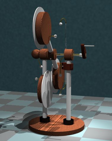
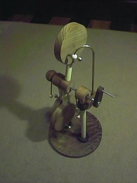
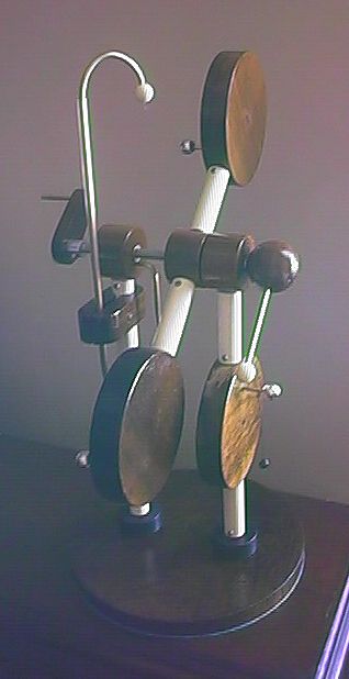
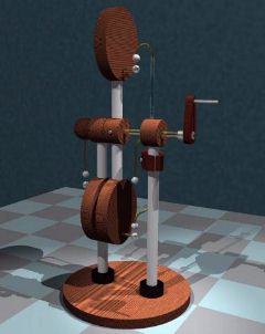 I completed a version of this machine
in October 1998. My machine uses wood disks with about 10 cm of
diameter and 2 cm thick. The insulators and upright supports are
1.5 cm PVC tubes, connected to the other pieces by little nylon
cylinders and two base pieces, fixed to the tubes by little
screws and to the wood blocks by inserting them in holes and
gluing. The pins and connections are made with 1/8" brass
bars, with 9 mm aluminum balls at the pins in the disks and
perforated plastic beads holding thin nickel-chrome wire loops
(avoiding points) making the four brushes. The base and the three
cylinders in the axle are made of wood, with a screw to fix the
rotating assembly to the spindle. The short-circuiting bar is
insulated by a plastic tube, and secured to one of the upright
supports by two wood pieces, fixed by a screw and a nut. Instead
of the large ball of the original design, I used a proportionally
small one, made of wood too, and connected the two ground
connections to the steel (3/16") spindle, one fixed,
touching the spindle through a hole in the ball, and the other in
contact with a brass washer in the spindle. Sections of plastic
tube and brass washers are used to keep the spindle in the
correct place relative to the upright supports.
I completed a version of this machine
in October 1998. My machine uses wood disks with about 10 cm of
diameter and 2 cm thick. The insulators and upright supports are
1.5 cm PVC tubes, connected to the other pieces by little nylon
cylinders and two base pieces, fixed to the tubes by little
screws and to the wood blocks by inserting them in holes and
gluing. The pins and connections are made with 1/8" brass
bars, with 9 mm aluminum balls at the pins in the disks and
perforated plastic beads holding thin nickel-chrome wire loops
(avoiding points) making the four brushes. The base and the three
cylinders in the axle are made of wood, with a screw to fix the
rotating assembly to the spindle. The short-circuiting bar is
insulated by a plastic tube, and secured to one of the upright
supports by two wood pieces, fixed by a screw and a nut. Instead
of the large ball of the original design, I used a proportionally
small one, made of wood too, and connected the two ground
connections to the steel (3/16") spindle, one fixed,
touching the spindle through a hole in the ball, and the other in
contact with a brass washer in the spindle. Sections of plastic
tube and brass washers are used to keep the spindle in the
correct place relative to the upright supports.
The machine self-excites easily, producing enough charge to be
clearly observable with an electrometer, or produce flashes in a
neon lamp touching the disks. Due to the low insulation between
the fixed disk and the others when they pass in front of it (just
0.5 cm of air), and the use of highly resistive wood disks, the
machine does not produce visible sparks. An electrometer connected
to the fixed disk shows high voltage when the two rotating disks
are at a horizontal position, and little or none when they are at
a vertical position (in one position the disk is grounded, and in
the other the disk forms a capacitor with a rotating disk,
"condensing" the charge). The operation of the doubler
is observable, with the electrometer showing approximately twice
the voltage at each turn after the excitation. After some cycles,
however, the voltage does not increase anymore, due to sparking
between the fixed disk and one of the rotating disks and other
losses (not visible). The machine then enters a steady state,
reaching approximately the same voltage at each turn, no more
than about 15 kV.
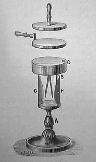
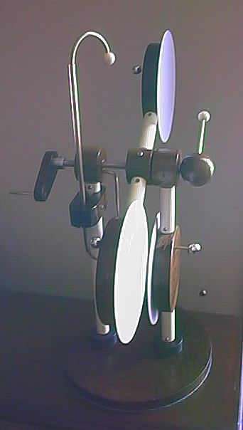
I found that it is possible to substantially increase the
output by gluing spark shields (plastic disks) in front of the
fixed and rotating disks. This picture
shows the modification, and here is a
photo of the final machine, and a comparison
of the output voltages obtained with and without the shields, as
measured by a simple electrometer. The machine sometimes reverts
the polarity, due to charge accumulation at the outer sides of
the spark shields. Sparks are now visible in the contacts when
the machine is excited. Disks made with a more conductive
material would probably be an improvement too, and would
certainly cause more visible sparking.
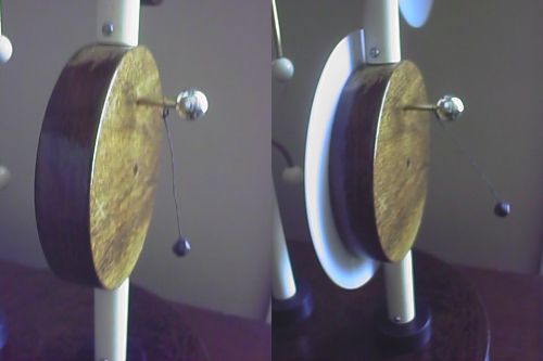
A picture of the machine, before the
varnishing of the parts, and after.
The thin insulation of the varnish over the fixed disk frequently
makes the electrometer ball stick to the disk.
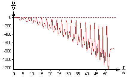 The plot at the left was obtained
connecting the fixed plate of the machine to an electrostatic
voltmeter connected to a computer with a data capture software
(Phywe elektrofeldmeter) and turning it slowly. The machine
charges the fixed plate with negative voltage that grows
exponentially at each turn. The negative peaks correspond to the
rotor at horizontal position, and the low voltages to the rotor
in a vertical position. The voltage reaches zero when the fixed
plate is grounded, and a low voltage when it is charging a
grounded rotor plate. The doubling at each cycle is incomplete
due to parasitic capacitances, specially the loading of the fixed
plate by the input capacitance of the electrostatic voltmeter.
The meter could measure only up to 1200 V with the setup used,
and so the measurement was stopped there. The output with
positive voltage is similar.
The plot at the left was obtained
connecting the fixed plate of the machine to an electrostatic
voltmeter connected to a computer with a data capture software
(Phywe elektrofeldmeter) and turning it slowly. The machine
charges the fixed plate with negative voltage that grows
exponentially at each turn. The negative peaks correspond to the
rotor at horizontal position, and the low voltages to the rotor
in a vertical position. The voltage reaches zero when the fixed
plate is grounded, and a low voltage when it is charging a
grounded rotor plate. The doubling at each cycle is incomplete
due to parasitic capacitances, specially the loading of the fixed
plate by the input capacitance of the electrostatic voltmeter.
The meter could measure only up to 1200 V with the setup used,
and so the measurement was stopped there. The output with
positive voltage is similar.
Created: 21 October, 1998
Last update: 4 April 2012
By Antonio Carlos M. de Queiroz
Return to Electrostatic Machines