A Big Wehrsen Machine (or a sectored
Holtz machine)
By August 2003, I could test a large Wehrsen electrostatic
machine, that I started building more than 2 years before. The
construction was interrupted for long periods, while I built a
smaller version to test the construction methods, and directed my
research about high-voltage generators to other directions, as
variations of the Tesla coil. A good introduction about the
Werhsen/Wommelsdorf machine is in the page about the prototype machine. The Wehrsen machine is
equivalent to a Holtz machine of the
first kind, using a rotating disk with internal sectors and
inductor plates encased in solid insulation. The machine, as
initially planned, didn't work adequately, and is now provisorily
working in a simplified form.
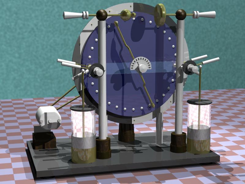
Original design for a Wehrsen machine
 The machine was constructed essentially
as a scaled-up version of the prototype,
but with some improvements in the construction methods and
variations due to the larger size. It had a fixed disk with 60 cm
of diameter, made with 3 mm black acrylic plate. Mounted on it
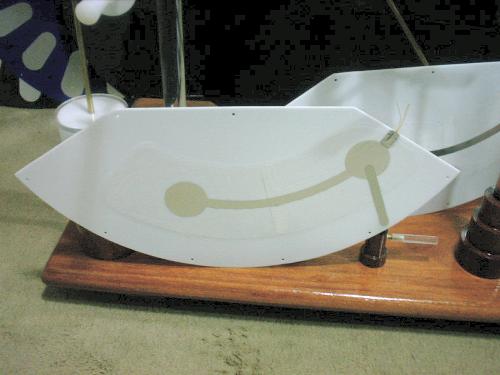
were two inductor plates, behind spark shields made with white
2.5 mm acrylic plates, fixed with screws to the back plate. The inductors had the same construction used
in Voss machines, made of varnished paper, with strips of
aluminum foil ended in disks at their centers to distribute the
charge. The paper and metal assemblies were then covered with two
layers of adhesive plastic foil, to ensure good insulation. The
complete encasing of the inductor plates is essential for this
construction, or the machine doesn't produce long sparks due to
leakage by corona around the spark shields. The rotating disk had
54 cm of diameter. It was built as a stack
of three 2.5 mm acrylic disks, with the two posterior disks
holding 16 sectors of adhesive aluminum tape each, interleaved.
The orientation of the three disks was selected for as uniform
weight distribution as possible, so the disk didn't vibrate
significantly even when rotated very fast. The 32 sectors were
accessed through buttons in the frontal disk. The buttons were
made of chrome-plated steel rivet heads, glued in place and
contacting the sectors through small springs. Due to the large
size of the disk, I could not glue the disks together with hot
glue, as I did in the prototype machine. I tried to just join the
disks with 8 small screws close to the edge of the disk, crossing
all three disks, leaving the insulation between the sectors made
by their separation alone. The effect of screws crossing the
three disks was difficult to predict, but I made the sectors
close to the screws a bit smaller, to increase the distance
between the sectors and the screws. The construction of the disk
in this way didn't work well. See below.
The machine was constructed essentially
as a scaled-up version of the prototype,
but with some improvements in the construction methods and
variations due to the larger size. It had a fixed disk with 60 cm
of diameter, made with 3 mm black acrylic plate. Mounted on it
were two inductor plates, behind spark shields made with white
2.5 mm acrylic plates, fixed with screws to the back plate. The inductors had the same construction used
in Voss machines, made of varnished paper, with strips of
aluminum foil ended in disks at their centers to distribute the
charge. The paper and metal assemblies were then covered with two
layers of adhesive plastic foil, to ensure good insulation. The
complete encasing of the inductor plates is essential for this
construction, or the machine doesn't produce long sparks due to
leakage by corona around the spark shields. The rotating disk had
54 cm of diameter. It was built as a stack
of three 2.5 mm acrylic disks, with the two posterior disks
holding 16 sectors of adhesive aluminum tape each, interleaved.
The orientation of the three disks was selected for as uniform
weight distribution as possible, so the disk didn't vibrate
significantly even when rotated very fast. The 32 sectors were
accessed through buttons in the frontal disk. The buttons were
made of chrome-plated steel rivet heads, glued in place and
contacting the sectors through small springs. Due to the large
size of the disk, I could not glue the disks together with hot
glue, as I did in the prototype machine. I tried to just join the
disks with 8 small screws close to the edge of the disk, crossing
all three disks, leaving the insulation between the sectors made
by their separation alone. The effect of screws crossing the
three disks was difficult to predict, but I made the sectors
close to the screws a bit smaller, to increase the distance
between the sectors and the screws. The construction of the disk
in this way didn't work well. See below.
The rotating disk was supported from behind only by a strong
turned wood support, having at the top a wood cylinder holding a
steel axle through two ball bearings. The disk was mounted on a
cylindric wood boss with three screws that pressed it against a
washer of flexible material, allowing precise adjustment of the
disk position for true rotation. I decided for manual operation
for the machine, as it allows better control during experiments.
In this machine I used commercial aluminum pulleys instead of
wooden pulleys, because they don't deform with time. The driving
cord was a sewing machine round leather cord.
The machine had two Leyden jars made with tall polyethylene
cups, with 200 pF each (maybe too much). Their outer plates were
interconnected with wires below the machine's base, with a small
spark gap at the center that can be used as pulsed output. The
jars could be switched on or off through switches connecting them
with the charge collectors. Other switches could connect the
charge collectors with the output terminals and with the inductor
plates, for startup. The switches were made all in the same way,
pivoting on brass cylinders that could rotate around the charge
collector tubes. They remained fixed at any position by friction,
created by rubber pads in the holes that hold the switch arms,
pressed against the tube by springs and metal pins mounted in
central holes in the arms. The charge collector brushes could be
moved in and out through handles at the front side of the
machine.
The frontal structure that holds the terminals was supported
by two acrylic round bars with turned wood bases, holding a
horizontal rectangular acrylic bar at the center, and continuing
as tubes. At the center of these tubes, aluminum tubes made the
connections with the terminals. The terminals were made by metal
spinning, in brass. The horizontal bars could slide on aluminum
tubes inside the wood bals that made the connection with the
upright supports. The horizontal acrylic bar holds the charge
collectors and the neutralizer bar.
The neutralizer and charge collector brushes were make with a
new technique, by wrapping a thin nickel-chrome wire around a
silicone monofilament line. The idea was to obtain a flexible
brush that doesn't break easily but stays in place. The result
was not very good, as the brushes were still breaking after some
time and were heavy enough to mark the disk. The buttons in the
frontal disk would then be better if almost at the level of the
disk, for minimal irregular pressing on the brushes. For the
brushes taking charge from the back of the rotating disk to
charge the inductors, as similar technique was used, but the
nickel-chrome wire was wrapped around silk threads, and fixed
with some glue. This resulted in lighter brushes and no problems.
Brushes like these at the front side didn't work well, because
they were easily moved away by the buttons in the disk
The first tests showed poor performance. The machine was
self-starting easily and producing the expected short-circuit
current (100 µA), but was not producing long sparks. The reason
for this I could trace to intense corona and sparking between
sectors in the spaces between the stacked disks, probably helped
by accumulation of ozone in the narrow spaces between the disks.
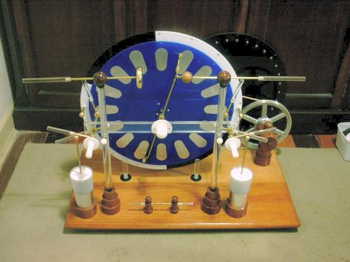
Testing the machine with the back disk
of the three only, it showed much better performance. It worked
even better with the central disk
alone, possibly because it was made with blue acrylic instead of
black. The holes in this disk didn't appear to be a problem. A
stack of the two sectored disks, without the frontal disk with
the buttons, worked a bit less well. With the three disks, the
performance was poor. Taking into account the good performance of
the prototype machine, it's evident then that a machine with
embedded sectors must have them really completely embedded in
solid insulation. The insulation of the inductor plates as I made
it, with adhesive plastic foil, is also not very satisfactory.
Significant leakage can be seen at the internal edges close to
the neutralizers, by looking at the machine in the dark. It's
really necessary to avoid bubbles in this construction. I can see
the bubbles under the foils lighting up in the dark..
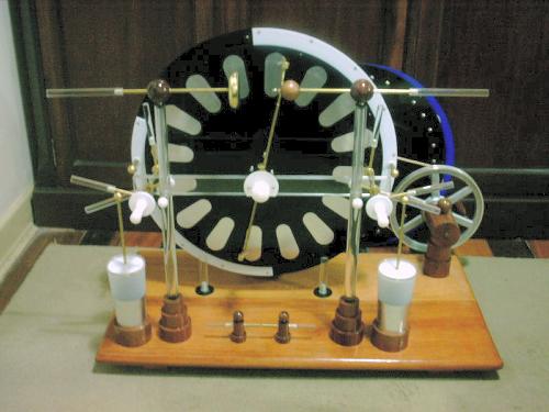
Sectored Holtz machine
 I decided then to abandon the
complicated rotating disk until I find an effective method to
join and seal the disks together without deforming them (also
because I deformed the back disk when trying to join the disks
with wax and heat...), and made a 55 cm Wimshurst-type disk with
transparent 3 mm acrylic, with 32 sectors. I would then have also
something to compare to the future disk with embedded sectors.
This disk worked as well as the sectored original disks. The
machine was then transformed in to a kind of sectored Holtz machine, with a startup
system as in the Wehrsen machine. The plate for the disk was not
very uniform, and I had to balance it by gluing a long string of
lead blocks to the lighter edge of the disk, a solution that I
have used in other machines, that although not very elegant is
simple and doesn't appear to introduce significant losses. The
alternative would be to sand one side of the disk until its
thickness is uniform and then polish the sanded area. A lot of
work. I mounted brushes made with silk threads wrapped with
nickel-chrome wire in the frontal brushes too, and they worked
well with the flat disk.
I decided then to abandon the
complicated rotating disk until I find an effective method to
join and seal the disks together without deforming them (also
because I deformed the back disk when trying to join the disks
with wax and heat...), and made a 55 cm Wimshurst-type disk with
transparent 3 mm acrylic, with 32 sectors. I would then have also
something to compare to the future disk with embedded sectors.
This disk worked as well as the sectored original disks. The
machine was then transformed in to a kind of sectored Holtz machine, with a startup
system as in the Wehrsen machine. The plate for the disk was not
very uniform, and I had to balance it by gluing a long string of
lead blocks to the lighter edge of the disk, a solution that I
have used in other machines, that although not very elegant is
simple and doesn't appear to introduce significant losses. The
alternative would be to sand one side of the disk until its
thickness is uniform and then polish the sanded area. A lot of
work. I mounted brushes made with silk threads wrapped with
nickel-chrome wire in the frontal brushes too, and they worked
well with the flat disk.
The startup system, by closing the switches that connect the
charge collectors with the inductor plates, can easily start the
machine even in very high humidity conditions (tested at 90% of
relative humidity in the air), but it's important to guarantee
good contact in the switches and in the connections to the
inductor plates. The machine works better when the inductor
plates are at a considerable distance, 1.5 cm, from the rotating
disk. The machine produced easily sparks with 18 cm of length,
eventually going to 20 cm. It's expected that in drier air it
will exceed this. The shape of the sectors leave a minimum
distance of 24 cm between the terminals, that is the expected
maximum spark length for the machine.
Created: 19/08/2003
Last update: 23/12/2003
Developed and maintained by Antonio Carlos
M. de Queiroz
Return to Electrostatic Machines