A Classical Tesla Coil with Top Load
Tuning
(or a 4th-order transformer-coupled
multiple resonance network with distributed load capacitance)
 After several experiments with variants
of the Tesla coil circuit, as a transformerless
circuit, a capacitively coupled
circuit, and a 6th-order directly
coupled circuit, I made this more usual version, using a
transformer. My main intention was to test the modeling of
inductances and mutual inductance, but I also wanted to see how
this method improves the performance of these.systems, by
allowing independence between the voltage gain and the energy
transfer time. The schematic diagram of the system is shown
below:
After several experiments with variants
of the Tesla coil circuit, as a transformerless
circuit, a capacitively coupled
circuit, and a 6th-order directly
coupled circuit, I made this more usual version, using a
transformer. My main intention was to test the modeling of
inductances and mutual inductance, but I also wanted to see how
this method improves the performance of these.systems, by
allowing independence between the voltage gain and the energy
transfer time. The schematic diagram of the system is shown
below:
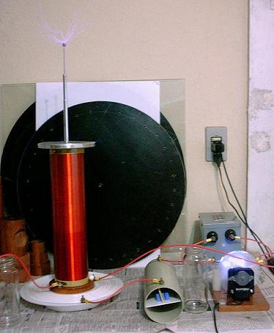
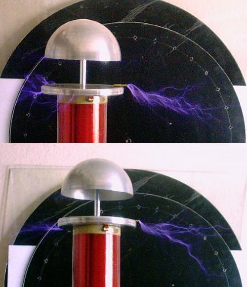
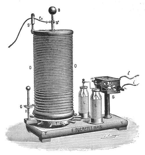
The circuit is a classical "Tesla coil", with the
only nonusual feature being that tuning is achieved by varying
the distributed capacitance of the top terminal, varying the
length of the antenna above it. This is the same method that I
used in my other systems.
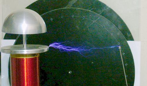
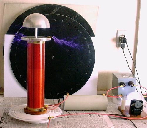
The circuit worked very well, producing streamers
and arcs to a grounded object that
easily reach 25 cm (specially when the
antenna is covered by a half sphere). Its performance is
significantly better to what I obtain with a directly
coupled system using the same elements, and more regular and
insensitive to tuning, certainly due to the faster energy
transfer.
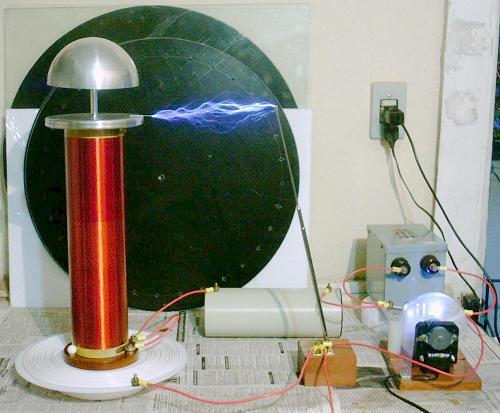
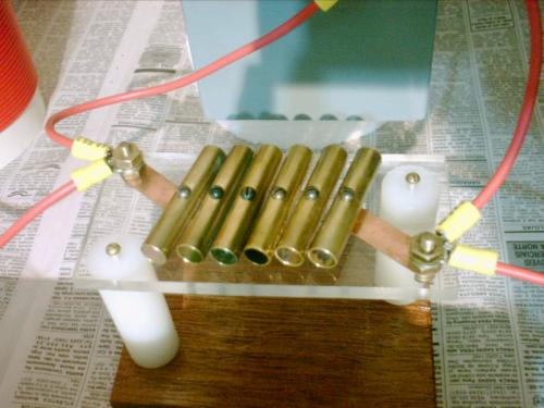
C1 (5.07 nF) and L2
(28.2 mH) are the same elements used in my other systems. The
neon sign transformer (5 kV, 30 mA) and the spark gap are also the same. L1
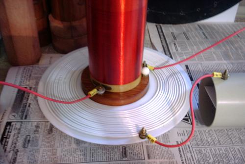
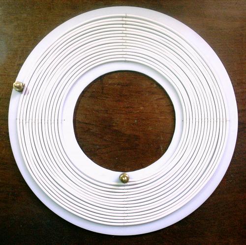
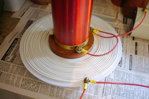
is a flat coil, made with insulated
#18 solid wire, with 14.7 turns, minimum radius = 7 cm, and
maximum radius = 12.5 cm. It was designed to have an inductance
of 58.7 µH, and a coupling coefficient with L2
of 0.105. This results in operation in mode 9:10, as my first directly coupled system, but with 5 times
bigger input energy.
Design:
This system was designed in the following way: First, the
operating mode k:l was selected. This ratio of
integers with odd difference (the usual is to have l = k+1)
determines the ratio of the two resonance frequencies of the
complete system (l/k), and the number of cycles
required for complete energy transfer (l/2 cycles of the
primary voltage). In this case the mode 9:10 was selected. The
coupling coefficient and the element values are obtained from the
equations [1]:
L1C1=L2C2=(k2+l2)/(2(w0kl)2)
k12=(l2-k2)/(k2+l2)
From the parameters of L2 (L =
28.2 mH, self-capacitance = 5.55 pF) and C1 (C
= 5.07 nF), and adding 5 pF, to account for the top terminal and
antenna, to the total capacitance C2 (C
= 10.55 pF), L1 is obtained as 58.7 µH, and w0/(2p),
the base frequency that multiplies k and l to
produce the two resonances, as 30.84 kHz. The two resonances are
then ideally at 277.58 kHz and 308.43 kHz. The separate pairs L1-C1
and L2-C2 resonate at
291.79 kHz. The required coupling coefficient is k12
= 0.105.
The secondary coil has 32 cm of length, 4.4 cm of radius, and
1152 turns of #32 wire. The primary coil dimensions can be
calculated from this version of Wheeler's formula for flat
spirals:
L = 100/2.54 ((r1+r2)N)2/(60r2-28
r1)
µH
where r1 is the internal radius, r2
the external radius, both in meters, and N is the number
of turns. Choosing r1 = 0.07 m and r2
= 0.125 m, 14.7 turns are required. The coupling coefficient was
calculated numerically by Neumann's formula,
implemented in my Teslasim program. In
this case the required coupling is obtained with L1
2.7 cm below L2. Since I mount L2
in a support that rises it by 3 cm, I mounted
L1 over a plastic disk with a hole for the
base of L2 at the center, "sewing"
the wire coil over the disk with silicone string. In this way L1
would stay at approximately the correct distance, and it would be
easy to adjust the distance by rising L1 or L2.
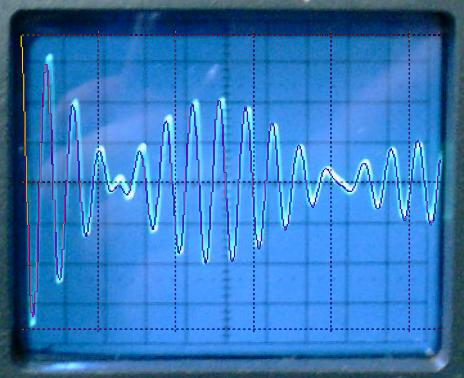
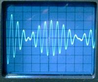 Measurements in the assembled system,
after proper tuning at low power, showed
that L1 ended a bit larger than calculated,
with 59.8 µH, and that the coupling was also increased, to
~0.12. The resonances were measured as 289 kHz for C1-L1,
and 270 kHz - 305 kHz for the whole system. The observed
waveforms put the operating mode between 7:8 and 8:9. The losses
caused by the tuner in the primary circuit cause some distortion
in the ideal waveform, explaining the apparent inconsistency
between the number of cycles before the first notch and until the
second notch. A simulation including 3
ohms of resistance in the primary circuit
agrees well with the observation. The increased primary
inductance can be atributed to wiring inductances in the setup
(it would be enough the complete the 15th turn to exceed the
measured inductance). The increased coupling may be due to
wiring, due to capacitive coupling (note that my capacitive transformer system has a
similar structure, but in this case the capacitance between L2
and L1 is very small), or, more probably, due
to the nonuniform current distribution in L2,
and even due to the presence of a shorted turn caused by the top
terminal, not considered in the calculations. It was easy to
adjust the system for correct operation in modes 7:8 or 9:10, by
moving L1 by less than1 cm. Actually, the
difference in efficiency between these modes or anywhere between
them is insignificant.
Measurements in the assembled system,
after proper tuning at low power, showed
that L1 ended a bit larger than calculated,
with 59.8 µH, and that the coupling was also increased, to
~0.12. The resonances were measured as 289 kHz for C1-L1,
and 270 kHz - 305 kHz for the whole system. The observed
waveforms put the operating mode between 7:8 and 8:9. The losses
caused by the tuner in the primary circuit cause some distortion
in the ideal waveform, explaining the apparent inconsistency
between the number of cycles before the first notch and until the
second notch. A simulation including 3
ohms of resistance in the primary circuit
agrees well with the observation. The increased primary
inductance can be atributed to wiring inductances in the setup
(it would be enough the complete the 15th turn to exceed the
measured inductance). The increased coupling may be due to
wiring, due to capacitive coupling (note that my capacitive transformer system has a
similar structure, but in this case the capacitance between L2
and L1 is very small), or, more probably, due
to the nonuniform current distribution in L2,
and even due to the presence of a shorted turn caused by the top
terminal, not considered in the calculations. It was easy to
adjust the system for correct operation in modes 7:8 or 9:10, by
moving L1 by less than1 cm. Actually, the
difference in efficiency between these modes or anywhere between
them is insignificant.
 An interesting observation is that the
effective coupling can be substantially changed if L2 is connected to one
side of L1, with the other side of L1
grounded. If I connect L2 to the center of L1
and ground its outer side, the mode decreases to close to mode 6:7, and there is a visible improvement in the performance.
Reversing the connections of L1 is also
possible, but it decreases the effective coupling. The observed
decrease was to mode 12:13. This
connection is knows as "Oudin coil",
and was first described in 1892. In this case, it was made with
two separate coils.
An interesting observation is that the
effective coupling can be substantially changed if L2 is connected to one
side of L1, with the other side of L1
grounded. If I connect L2 to the center of L1
and ground its outer side, the mode decreases to close to mode 6:7, and there is a visible improvement in the performance.
Reversing the connections of L1 is also
possible, but it decreases the effective coupling. The observed
decrease was to mode 12:13. This
connection is knows as "Oudin coil",
and was first described in 1892. In this case, it was made with
two separate coils.
An Oudin coil with inductances L1 and L2,
and coupling coefficient M, can be transformed into an
equivalent Tesla coil by the aplication of the "T"
equivalent of a transformer twice, as shown below:
The result is a Tesla coil with the parameters:
L1'=L1
L2'=L1+L2+2M
M'=L1+M
k12'=(L1+M)/(L1(L1+L2+2M))1/2
In the example, using the observed k12 =
0.12, k12' = 0.16, corresponding closely to a
bit less than the observed mode 6:7. The reverse connection
corresponds to a negative M, what gives k12'
= 0.075, corresponding to a bit more than the observed mode
12:13.
Programs that can design and simulate the behavior of this
system, and others, can be found here.
Extensive materials about Tesla coils can be found in the
archives of the Tesla list.
A short video
with a demonstration of the device in operation in March 2006.
[1] See the papers about "multiple resonance
networks" here.
Warning:
This device is powered by a
power source that has enough voltage, and specially enough
current, to give a fatal shock. The NST, the terminals of C1,
L1,
and the spark gap must not be touched in any circunstance while
the system is energized. The high-voltage arcs are also not safe
to touch. They may cause burns, and the current is intense enough
to cause internal body damage.
Created: 28 February 2003
Last update: 5 April 2006
Created and maintained by Antonio Carlos
M. de Queiroz
See also: Electrostatic Machines