 Continuing the studies about
directly coupled multiple resonance networks operated as Tesla
coil like devices, I built a 6th-order system, that is equivalent
to a "Tesla magnifier",
but without a transformer. The schematic diagram is shown below:
Continuing the studies about
directly coupled multiple resonance networks operated as Tesla
coil like devices, I built a 6th-order system, that is equivalent
to a "Tesla magnifier",
but without a transformer. The schematic diagram is shown below:A directly coupled "Tesla magnifier"
(or a 6th-order transformerless multiple resonance network with distributed load capacitance)
Continuing the studies about
directly coupled multiple resonance networks operated as Tesla
coil like devices, I built a 6th-order system, that is equivalent
to a "Tesla magnifier",
but without a transformer. The schematic diagram is shown below:
This circuit has several potential advantages over a simpler directly coupled Tesla coil: Faster energy transfer from C1 to the distributed terminal capacitance C3, what results in smaller losses, greater efficiency, and insensitivity to tuning precision. The wider notches in the primary waveforms tend to cause fast quenching of the spark gap, at the first notch, trapping all the energy in the high-voltage part of the circuit. The design is restricted by the absence of the extra degree of freedom allowed by a transformer in the classic magnifier circuit, with the maximum voltage gain being forced by the ratios among the resonance frequencies, but the transformerless construction is simpler.
The system was designed to have three resonance frequencies, in the ratio 5:6:7. In this way it can transfer the energy in C1 to C3, ignoring losses, in just three cycles (in 12.5 µs), instead of in the 11 cycles (in 37.6 µs) required by the 4th-order directly coupled system with the same input (identical) and output (almost identical) capacitances.
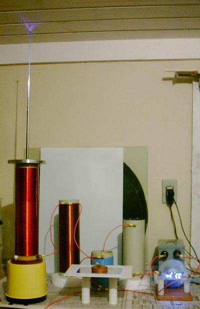
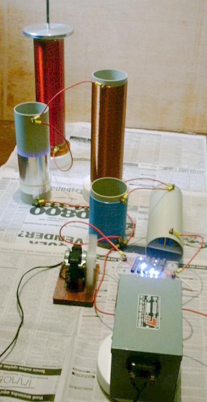
The power supply is a 5000 V, 30 mA neon sign transformer with a single floating output, that charges the capacitor C1, that is then discharged through a multiple spark gap starting the energy transfer transient. C1 is a 5.09 nF "MMC" capacitor, the same that I used with the 4th-order system. L3, the output resonator coil with 28.2 mH, the terminal with a telescopic antenna, the NST and the spark gap are also the same. Their description can be seen here.The other two coils are L1, with 87 µH, made with 42 turns of insulated 1 mm2 wire over an 8.8 cm PVC tube, and L2, with 1521 µH, made with 257 turns of #18 magnet wire, also over a PVC tube. C2 is a flat plate high-voltage capacitor, that produced the best tuning with the other elements with 257 pF. No filters or special protection circuits were included, since the power is not high. The ground connection goes to just a metal bucket in the ground. The components are simply disposed over a table, interconnected with flexible wires with terminals at the ends, between brass screws and nuts mounted in the elements. Insulating supports are inserted below the floating elements.
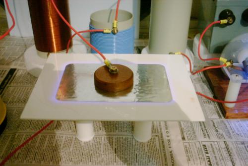
C2 was, in a first attempt, an adjustable capacitor made with a PVC tube having a fixed inner plate of aluminum foil and an adjustable outer plate. Worked well at low power, but when in operation at full power the construction resulted in a lot of corona, and progressive capacitance change due to surface deterioration of the PVC, probably with metal deposition, that increased the capacitance and detuned the system. When I tried to improve the insulation by applying wax around the edges of the plates, it failed almost immediately with a puncture. A new capacitor was then made with simply two flat plates glued to an acrylic plate, in contact with terminals fixed to the plates, with the dimensions calculated to result in 247 pF. But due to an error (I disconsidered the fringe field at the borders of a test capacitor made to determine the dielectric constant of the acrilic plate) it resulted smaller, with 211 pF. I realized, however, that corona around the plates would increase the effective capacitance by approximately the correct amount. The capacitor worked well. I didn't try to improve its insulation in the first tests (and the plates would have to be a little larger without the corona).
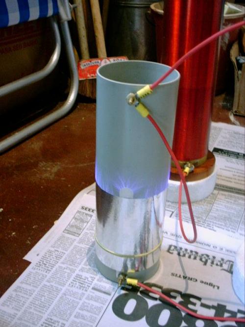
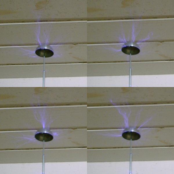
The obtained performance was somewhat better than with the 4th-order system, a fact evidenced by the presence of streamers coming not only from the terminal antenna, but also from the disk at the base of the terminal. It also produces a kind of corona haze around the terminal that was not observed in the simpler system. It's also evident that the spark gap runs cooler and in a more stable and less noisy way. The blower shown in the picture, behind the gap, is not really necessary. The output is not as sensitive to the length of the antenna (and the capacitance C3) as in the 4th-order system. Streamers can be obtained from the terminal even covering the tip of the antenna with a half-sphere with greater radius of curvature. Arcs to grounded targets can reach maybe 20 cm. The capacitor C2, with all that corona, is dissipating some energy, but the system works very well even with this.
Design:
This system can be designed using the "multiple resonance network" theory [1]. The idea is to have all the energy initially stored in C1 transferred to C3 after a few oscillation cycles, with zero voltages and currents in the other elements at the instant when the transfer is complete. Select first the ratio of the three resonance frequencies, as three integer numbers k, l, and m having odd differences, that define the operating mode. In this case I used the k=5, l=6, and m=7, mode 5:6:7. The mode is selected based on the resulting element values, specially on the capacitor ratio that defines the voltage gain. A faster mode, with lower multipliers, results in greater efficiency, but lower voltage gain. Since I had C1, I just selected the fastest mode resulting in a realizable C3 A normalized design, with C3=1 and resonances at k, l, amd m rads/s can be obtained from the formulas below:
The voltage gain is:
To obtain the final required values, it's possible to start from a measured secondary coil L3final and an available C1final, since these are more difficult to adjust, and compute L1final, L2final, C2final, and C3final keeping the same ratios:
L1final = L1L3final/L3
L2final = L2L3final/L3
C2final = C2C1final/C1
C3final = C3C1final/C1
In my example, starting from k=5, l=6, m=7, L3final=28.2 mH, and C1final=5.09 nF, the results are:
Normalized circuit:
C3= 1 F
L3= 0.0277778 H
C2= 18.1258741 F
L2= 0.0015319 H
C1= 328.8008705
F
L1= 0.0000894 H
Final circuit:
C3final =
15.4805 pF
L3final = 28200
µH
C2final =
280.5975 pF
L2final =
1555.1870 µH
C1final =:5090 pF
L1final = 90.7721 µH
C3 can be adjusted by the length of the antenna in the terminal (almost full length for best results). The system oscillates at kf0, lf0, and mf0 where:
f0 = (1/(2p))(L3C1/(L3finalC1final))1/2 = 40.1469 kHz.
And so, kf0 = 200.7 kHz, lf0 = 240.9 kHz.and mf0 = 281.0 kHz. Total energy transfer occurs in 1/(2f0) = 12.5 µs, after 3 apparent full cycles of the voltage over C1.
The actual measured values of the calculated elements were L1=86.61 µH and L2=1521 µH. C2 was determined experimentally, since it absorbs capacitances of L2, L3, and of the interconnections. The best value was found to be 247 pF, and the fixed capacitor was designed to this value.
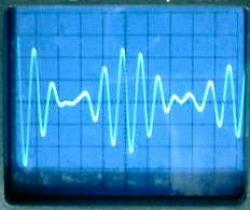
Voltage waveforms:
Below are shown the voltage waveforms observed over C1, C2, and C3, in a low-power test, with the power supply and the spark gap replaced by a low-impedance square-wave generator. VC1 (left) and VC2 (center) were measured directly. VC3 (right) was measured by placing the oscilloscope probe close to the terminal, without touching it. 3 cycles or VC1 are required for complete energy transfer, showing that the system is operating very close to mode 5:6:7. Ideal waveforms.


[1] A. C. M. de Queiroz, "Multiple resonance networks," IEEE Transactions on Circuits and Systems I, Vol. 49, No. 2, February 2002, pp. 240-244.
See more references about multiple resonance networks here. The program Multires can make all the design calculations for this circuit and other low-pass multiple resonance circuits of different orders and modes..
Warning:
This device is powered by a power source that has enough voltage, and specially enough current, to give a fatal shock. The NST, the terminals of C1, L1, and the spark gap must not be touched in any circunstance while the system is energized. The other areas and arcs from the terminal can also produce serious burns and are also not safe to touch.
Created: 13 November 2002
Last update: 15 September 2005
Created and maintained by Antonio Carlos
M. de Queiroz
See also: Electrostatic Machines