
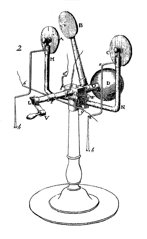
This "doubler" was proposed by William Nicholson, London, in 1788, in a paper in the Philosophical Transactions entitled "A description of an instrument which by the turning of a winch produces the two states of electricity, without friction or communication with the earth." (See also [p106].) This is considered the first automatic rotating machine built to generate electricity by influence.

The ball D serves as "ground" through its distributed capacitance (there is no ground connection in the machine), and may also serve to hold a weight inside it to counterbalance the weight of the plate B.
With this disposition, the same operations of Bennet's doubler can be done automatically as the crank is turned. With the machine in the initial position, with plate A initially charged, opposite charges are attracted to the plates A and B, leaving C practically uncharged. The charge in plate B is taken from the sphere::
When the crank is turned 180 degrees, the charge in plate B is replicated, inverted, in plate C, coming from the sphere:

When one turn of the crank is completed, the charges in A and B accumulate in A, and B gets charged with an inverted copy of the sum of both charges, coming from the sphere. All the charges are doubled:
The charges in A and B double at each turn of the crank. In practice the doubling is not perfect (but very close), and the process goes on only until a spark (between A and B or B and C) discharges the plates. The process then starts again from remaining charges.
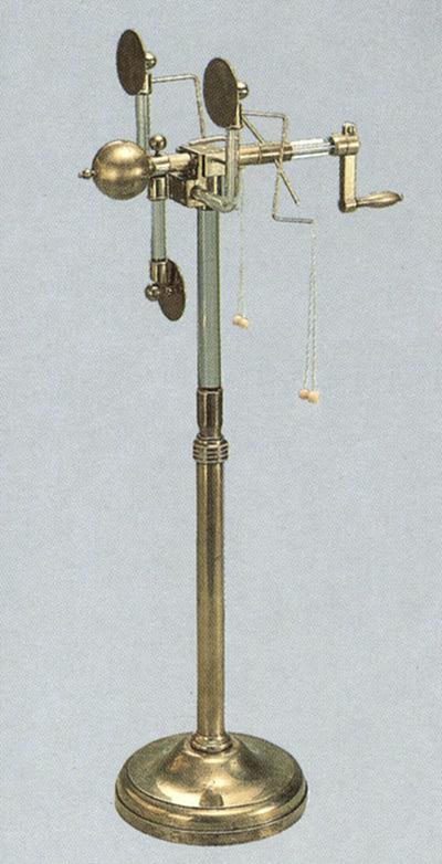
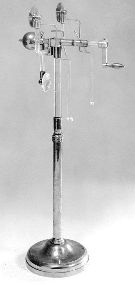
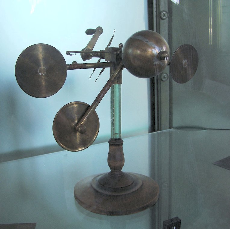
Some original machines still exist, as this in the Teyler's Museum. A similar doubler (appears to be John Read's doubler [p106]) can be found at the Musee d'histoire des sciences, in Geneva, Switzerland. Another picture, from this booklet. There was a movie of the machine in operation too some time ago. Alessandro Volta used this doubler, that is now at the Tempio Voltiano, in Como, Italy.
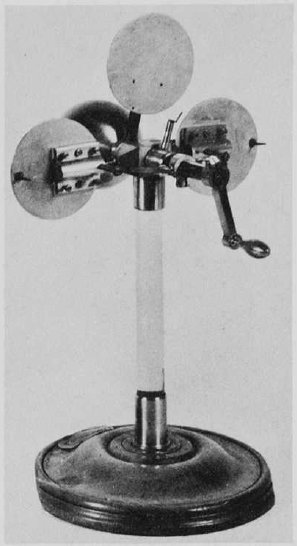
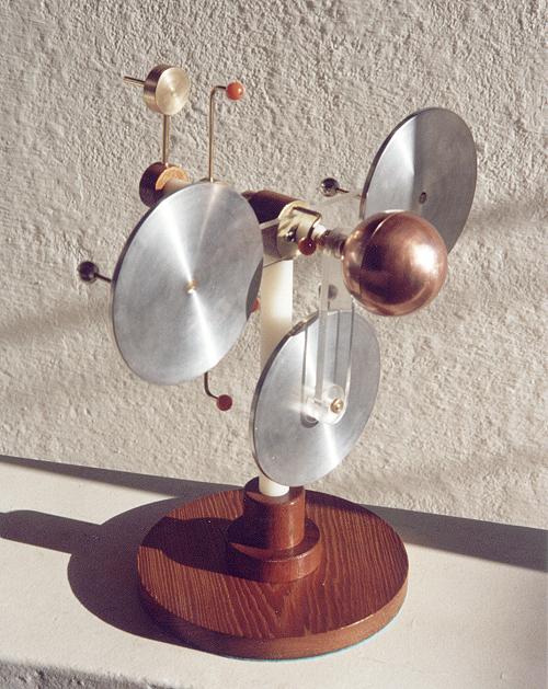
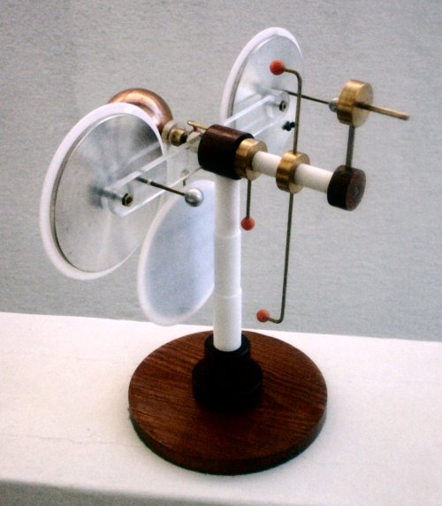
A model of Nicholson's doubler
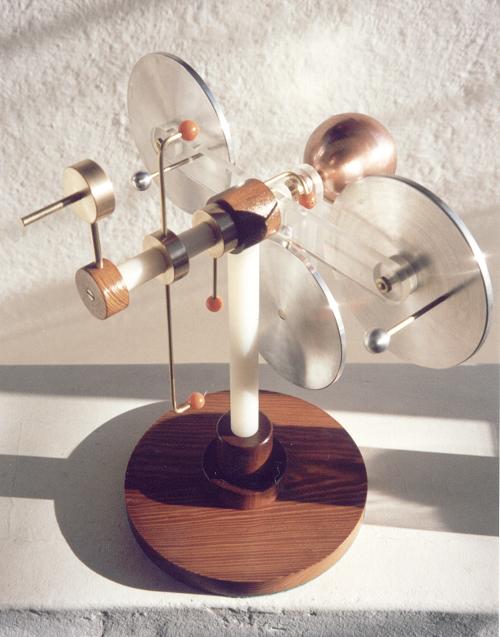
In July 2000 I completed a model of Nicholson's doubler. I didn't expect great surprises, since this machine operates exactly as Bennet's doubler and Bohnenberger's machine, both of them I had already made. Doublers are weak influence machines, producing much less charge than machines based on different ideas as Faraday's "ice pail" concept and the "continuous electrophorus". I wanted something capable of producing visible sparks, what my other doublers, using wood plates, don't make. I started with three thick aluminum disks, cut from a plate and finished in the lathe. Plates A and B were fixed to an acrylic bar through screws and nuts at their centers, and plate C was mounted in the same way in an arm fixed to the rotating central axle. A brass axle was used, completed by a Nylon cylinder for the insulating section connected to the handle. The ball was made of copper sheet by metal spinning, in two halves, joined by gluing the halves over a wood disk inside the ball. A screw crossing the wood disk and one of the halves provides a solid mounting for the ball, screwed at a thread cut at the end of the axle. I had the intention of mounting lead blocks inside the ball to counterbalance the weight of the rotating plate, but I found that this would require too much weight at the frontal part of the machine. I left then it unbalanced, adding only a heavy bronze block to the crank to partially balance it. The central support was made as a wood cylinder, mounted over a 2 cm Nylon bar inserted in a solid wood support. The base is a nice disk of Riga pine, cut from an old board salvaged from a reform in my house. The brushes were mounted in brass bars and bronze rings, and were all made of rings of nickel-chrome wire fixed in place by plastic beads.

The machine self-excites as the other doublers, requiring 10 to 30 turns to reach saturation. The metal construction produces clearly audible sparks at the brushes, visible in the dark, and sometimes a discharge spark after some time. As there is no added capacitance, other than the body capacitance of the plates, these discharges are not strong, but can be easily felt if I approach a finger from a charged plate. The sparks produced in this way have only about 2-3 mm. The machine doesn't reach very high voltage, because the disks move in parallel after getting charged by the brush contacts. The voltage rises fast when they move apart, but the distance between the disks remains small, and soon a spark discharges the plates. I added plastic disks in front of the metal plates as spark shields, resulting in some improvement. Even so, the brushes, free in the air, can discharge the plates at some distance by corona emissions. Charge accumulation on the outer surfaces of the spark shields causes the machine to revert polarity after some time, if turned slowly. The structure of this doubler allows the generation of continuously increasing charges at plate A, that can be used as output of the machine, for charging a Leyden jar capacitor, for example. The same can be done with the electroscope plate in Bennet's doubler, but is not practical in Bohnenberger's machine, that has the equivalent plate turning.

Pictures from the actual machine:
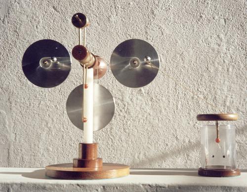
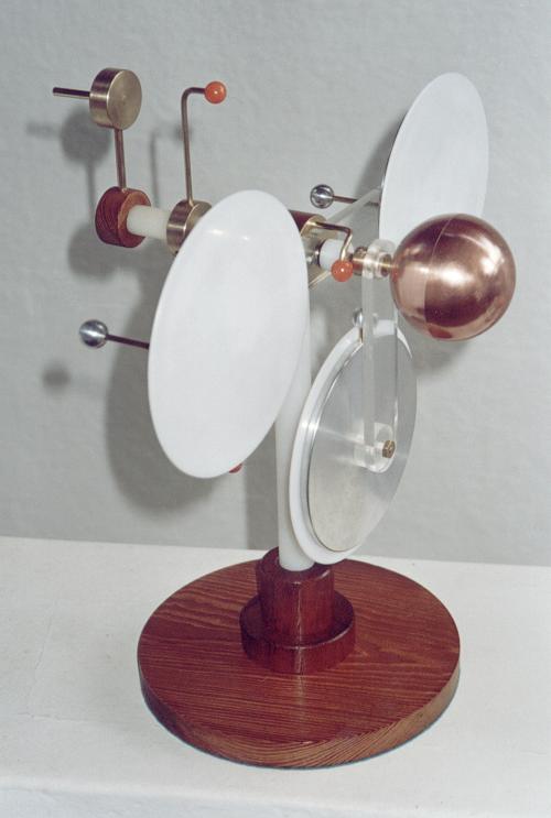
Frontal view, back
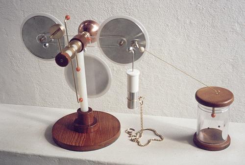
view, charging an electroscope, with spark
shields in place, and charging a Leyden jar.
By April 2004, the machine has ceased to work because the Nylon insulators had become too conductive. I then replaced them by Teflon rods, that are practically perfect insulators, and the machine worked again, now reaching saturation in just 10 cycles. I also used a thicker support to make the machine more firm.
A video of the machine in operation.
Nicholson's spinning multiplier
Nicholson invented also another multiplier, said to avoid the problems of generating electricity spontaneously presented by the doubler. The original description of the instrument can be seen here. An instrument that may be the original one, or a similar reproduction, can be seen at the Teylers Museum.Created: 31 July 2000
Last update: 25 April 2016
Developed and maintained by Antonio Carlos
M. de Queiroz.
Return to Electrostatic Machines