When studying Wilson's
machine I noticed that one of its plates (the rightmost in the
drawing) is just a contact point, and that the central accumulator
plate is not necessary. Without these plates the machine is just a
different version of Bennet's doubler, with
an interesting mechanism. The other mechanical versions of Bennet's
doubler that I had made all moved the disks laterally, what causes
charge accumulation at the sides of the disks and prevents the
achievement of very high voltages, due to sparking caused by the
intense lateral electric fields. A machine built in this way moves the
disks almost along their axles, and should be less sensitive to
excessive charge accumulation at the edges of the disks. This
mechanical construction also differs from the others because there are
no moving contacts. A rotating version of
the same idea resulted in other doubler that I made some time
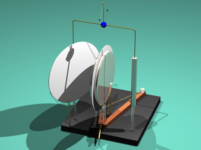
before, that works quite well. So, by July 2007 I built a version of
this "simplified Wilson's machine". I used three large disks, with 20
cm of diameter, made of plywood covered with aluminum tape, supported
by acrylic rods, and with contact posts and other elements made of
brass. The base was made of plywood, and the levers of wood. I added
also a double ball electrometer in the top connection bar, that serves
as output terminal. With the large disks I was expecting to obtain
visible sparks at the contacts with the machine charged. The machine
has one fixed disk, corresponding to the leftmost disk of Wilson`s
machine, the two movable disks mounted in the reciprocating levers,
and a cylinder replacing the rightmost disk. The gounding posts are as
in Wilson's machine.
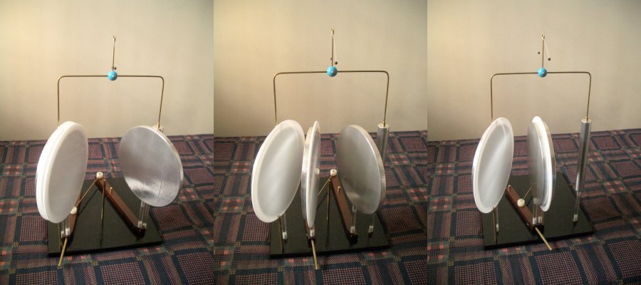
The final machine worked as expected
for a Bennet's doubler, self-exciting from discharged plates to full
charge in at most 20 cycles. It clearly works better than my other
mechanical doublers. The mechanical construction is not very practical
at this size, could be more solid, but the machine is still easy to
operate. When fully charged, small sparks can really by seen when the
plates approach the grounding posts and the cylinder, and are clearly
audible. The maximum voltage appears to be something around 20 kV. The
square edges of the plates, the presence of the grounding posts close
to the disks, the electrometer with small balls, and charge
accumulation in the spark shields prevents further increase. I
installed just two spark shields. Maybe better results could be
obtained with the use of pairs of spark shields, one at each plate on
the faces that come close without touching, but this would complicate
the installation of the grounding posts.