

| xPC Target | |
The Receive driver block is used to retrieve data from a CAN-network to be used within a block model. You can use as many instances of the Receive block in the model as needed. For example by using two instances of the block with different sample times, CAN messages can be retrieved at different rates. Or you can use multiple instances to structure your model more efficiently.
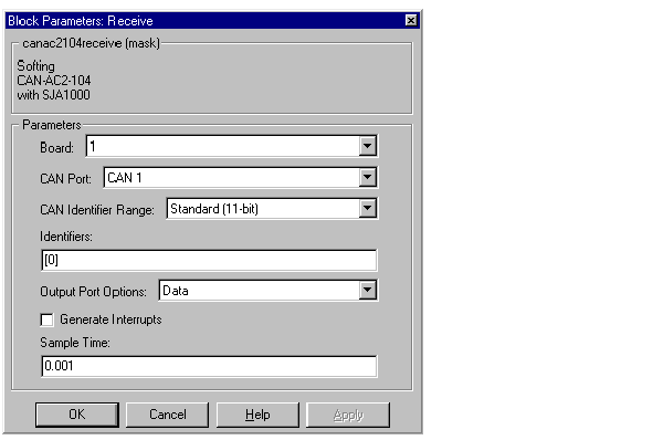
The dialog box of the block lets you define the following settings.
Board -- The first control (pop-up menu) lets you define from which physically present board the CAN messages defined by this block instance are retrieved from. For more information about the meaning of the board number see the Setup driver block described above. If just one board is present in the target system, board number 1 should be selected.
CAN Port -- The second control (pop-up menu) is used to select from which CAN port, the CAN messages will be retrieved from.
CAN Identifier range -- The third control (pop-up menu) is used to select the identifier range of the CAN messages retrieved by this block instance. If an application makes use of mixed Standard and Extended identifier ranges, at least two instances of this block have to be used, each defining the corresponding identifier range.
Identifiers -- The fourth control (edit field) is used to define the identifiers of the CAN messages retrieved by this block. It has to be a row vector where the elements define a set of either Standard or Extended identifiers. Each element has to be in the range between 0 and 2031 for Standard identifiers or 0 and 229 - 1 for Extended identifiers. The number of identifiers for each CAN port in a model per physical CAN board cannot exceed 200 (restriction of the firmware's dynamic object mode). The number of elements defined here, define at the same time the number of output ports of the block. The block icon displays the selected identifier at each output port. Each output port will output the data frame being retrieved along with the CAN message. The signal leaving each output port is a scalar of type double representing the maximum size of 8 bytes of a CAN-message's data frame.
Output port options -- The fifth control (pop-up menu) lets you define which type of retrieved data is output at each output port. Three different types of data can be output, which are data frame, status and timestamp. The status information is of type double and is identical to the return value of function CANPC_read_rcv_data(...) described in the Softing user manual. Refer to the manual for more information. The timestamp information is of type double and outputs the latest time at which a CAN message with the corresponding identifier has been received. This time information in seconds (with a resolution of 1 microsecond) can be used to implement time-out-logic within your model.
The pop-up menu lets you select which output information is output at each output port of the block. If "Data" is selected each output port signal is a scalar only. If "Data - Status" is selected each output port signal is a vector with two elements, where the first element contains the data frame and the second element the status information. If "Data - Status - Timestamp" is selected each output port signal is a vector with three elements, where the first element contains the data frame, the second element the status information, and the third element the timestamp.
Generate interrupts -- The sixth control (check box) lets you define if the CAN messages defined in this instance of the block will initiate an interrupt from the CAN board each time they are received. If checked this allows driving the model (target application) execution controlled by CAN messages.
Sample time -- The seventh control (edit field) defines the sample time at which the Send block is executed during a model (target application) run.
| | Send Driver Block | Constructing and Extracting CAN Data Frames | |