| xPC Target | |
Marking Block Signals
Tagging signals in your Simulink model allows the function xpcsliface to create From xPC Target interface blocks. These interface blocks contain the signals you connect to display devices (gauges) in your user interface model.
After you create a Simulink model, you can mark the block signals. This procedure uses the model xpc_tank1.mdl (or xpctank.mdl) as an example. See Creating a Target Application Model.
Notice that you cannot select signals on the output ports of any virtual blocks such as Subsystems and Mux blocks. Also, you cannot select signals on any Function-call, triggered signal output ports.
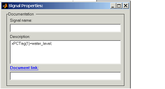
The tag has the following syntax:
For single dimension ports, the following syntax is also valid:
To create the From xPC blocks in an user interface model for a signal line with four signals (port dimension of 4), use the following syntax:
To create the From xPC blocks for the second and fourth signals in a signal line with at least four signals, use the following syntax:
You next task is to mark block parameters if you have not already done so, and then create the user interface template model. See Marking Block Parameters and Creating a User Interface Model.
| | Marking Block Parameters | Description of the User Interface Model | |