| Real-Time Windows Target |
  |
Creating a Simulink Model
This procedure explains how to create a simple Simulink model. You use this model as an example to learn other procedures in the Real-Time Windows Target.
You need to create a Simulink model before you can run a simulation, or create a real-time application:
- In the MATLAB command window, type
- The Simulink Library Browser window opens.
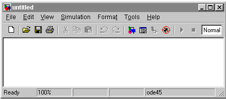
- From the toolbar, click the Create a new model button.

- An empty Simulink window opens.

- In the Simulink Library Browser window, double-click Simulink, and then double-click Sources. Click-and-drag Signal Generator to the Simulink window.
- Double-click Continuous. Click-and-drag Transfer Fcn to the Simulink window.
Double-click Sinks. Click-and-drag Scope to the Simulink window.
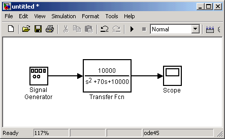
- Connect the Signal Generator output to the Transfer Fcn input by clicking-and-dragging a line between the blocks. Likewise, connect the Transfer Fcn output to the Scope input.
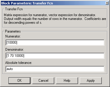
- Double-click the Transfer Fcn block. The Block Parameters dialog box opens. In the Numerator text box, enter
- In the Denominator text box, enter
Your Block Parameters dialog box will look similar to the figure shown below.

- Click OK.
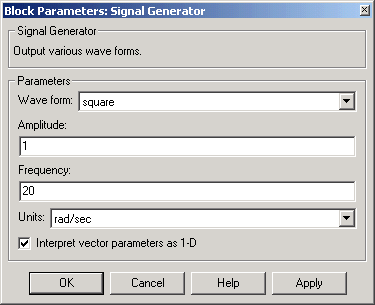
- Double-click the Signal Generator block. The Block Parameters dialog box opens. From the Wave form list, select
square.
- In the Amplitude text box, enter
In the Frequency text box, enter
From the Units list, select rad/sec.
Your Block Parameters dialog box will look similar to the figure shown below.

- Click OK.
- The completed Simulink block diagram is shown below.

- From the File menu, click Save As. The Save As dialog box opens. In the File name text box, enter a filename for your Simulink model and click Save. For example, type
- Simulink saves your model in the file
rtwin_model.mdl.
 | Simulink Model | | Entering Simulation Parameters for Simulink |  |


