
| Real-Time Windows Target |   |
Entering Signal and Triggering Properties
Data is saved to the MATLAB workspace through a Simulink Scope block. Signal and triggering properties need to be set only when running a real-time application. If you are running a simulation, you can skip this procedure.
After you create a Simulink model and add a Scope block, you can enter the signal and triggering properties for logging to the MATLAB workspace. This procedure uses the Simulink model rtwin_model.mdl as an example and assumes you have already loaded that model:
manual. From the Mode list, choose normal.
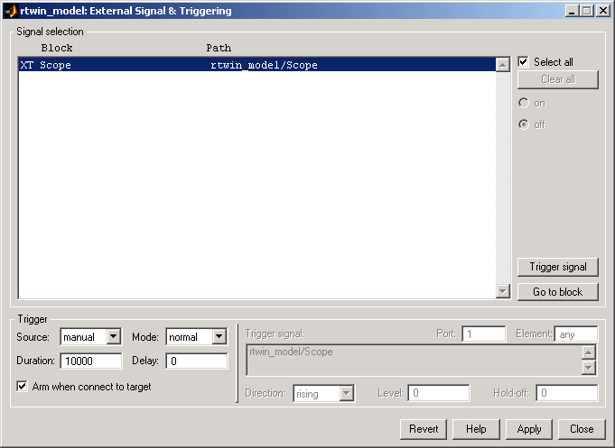
X under Signal selection designates that a signal has been tagged for data collection, and T designates that the signal has been tagged as a trigger signal.
To clear the Limit data points to last check box, see Entering Scope Parameters.
The Duration value specifies the number of contiguous points of data to be collected in each buffer of data. We recommend that you enter a Duration value equal to the total number of sample points that you need to collect rather then relying on a series of buffers to be continuous.
If you enter a value less than the total number of sample points, you will lose sample points during the time needed to transfer values from the data buffer to the MATLAB workspace. The Real-Time Windows Target ensures that points are continuous only within one buffer. Between buffers, due to transfer time, some samples will be omitted.
We also recommend setting the time axis for Simulink Scope blocks equal to the sample interval (in seconds) times the number of points in each data buffer. This setting will display one buffer of data across the entire Simulink Scope plot.
The Signal & Triggering dialog box will look similar to the figure below.

 | Entering Scope Parameters | Plotting Logged Signal Data |  |