| Real-Time Windows Target |
  |
Digital Input Block
The Real-Time Windows Target I/O blocks allow you to select and connect specific digital lines or digital channels to your Simulink model.
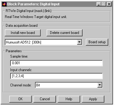
After you have added and Digital Input block to your Simulink model, you can enter the parameters for this I/O driver. This procedure uses Humusoft's AD512 I/O board as an example:
- Double-click the Digital Input block.
- The Block Parameters: Digital Input dialog box opens.
- In the Sample time box, enter the same value you entered in the Fixed step size box from the Simulation Parameters dialog box. For example, enter
- In the Input channels box, enter a channel vector that selects the digital input channels you are using on this board. The vector can be any valid MATLAB vector form. For example, to select all eight digital input channels on the AD512 board, enter
[1,2,3,4,5,6,7,8] or [1:8]
- If you want to use the first four digital input lines, enter
If you have one 8-bit digital channel, enter [1]. If you have two 8-bit digital channels, enter [1 9], and from the Channels mode list, choose Byte.
- From the Channel mode list, choose one of the following options:
Bit -- Returns a value of 0 or 1
Byte -- Groups eight digital lines into one digital channel and returns a value of 0 to 255.
- If you chose
Bit, your dialog box will look similar to the figure shown below.

- Do one of the following:
- Click Apply to apply the changes to your model and leave the dialog box open.
- Click OK to apply the changes to your model and close the Block Parameters: Digital Input dialog box.
 | Analog Output Block | | Digital Output Block |  |


