

| Target Language Compiler | |
Code Data Structure Concepts
In general, a block diagram is encoded using one or more of the following model data structures:
The model data structures are layered out according to the model hierarchy and the length is limited to at most 7 characters to allow us to stay within the 31 identifier character limit.
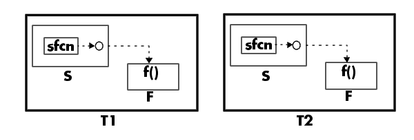
The layout includes function-call systems that reside in a parent system of their caller. For example, in the following model, subsystems T1 and T2 are structurally the same:
typedef struct rtB_S_tag {
  <block outputs in S>
} rtB_S;

typedef struct rtB_F_tag {
  <block outputs in F>
} rtB_F;

typedef struct rtB_T_tag {
  <regular (non system) block outputs in T>
  rtB_S  s;
  rtB_F  f;
} rtB_T;

typedef struct rtB {
  <regular (non system) block outputs in root>
  rtB_T t1;
  rtB_T t2;
}
This nesting of the block I/O data structure concept is applied to the other model structures (e.g., DWork). For the case of inline parameters off, the generated code will look roughly like:
F(f_input_signals, rtB_F *rtB, rtP_F *rtP)
{
  ...
}

S(s_input_signals      , rtB_S *rtB   , rtP_S *rtP,
  s_input_signals_for_F, rtB_F *rtB_F1, rtP_F *rtP_F1)
{
  ...
  F(f_input_signals, rtB_F1, rtP_F1)
  ...
}

T(t_input_signals, rtB_T *rtB, rtP_T *rtP)
{
  ...
  S(s_input_signals, &rtB->s, &rtP->s,
    s_input_signals_for_F, &rtB->f, &rtP->f)
  ...
}

MdlOutputs()
{
   ...
   T(t1_input_signals, &rtB.t1, &rtP.t1);  // outputs are passed via rtB.t1
   ...
   T(t2_input_signals, &rtB.t2, &rtP.t2);  // outputs are passed via rtB.t2
   ...
}
| | General model.rtw Concepts | Inline Parameters On Code Structure | |