| Requirements Management Interface |
  |
Viewing the Requirements for a Node
Use the Navigator to see which nodes have requirements associated with them. This is done when you are reviewing the objects (Simulink model, Stateflow diagram, or MATLAB M-file) requirements.
Select a node that has requirements associated with it. The requirements for that node appear in the right pane of the Navigator.
The shading of a node's icon in the Navigator indicates whether or not it has associated requirements, as shown in the following table.
Table 2-1: Node icons in the Navigator and What They Represent

|
Not shaded
|
Simulink subsystem with no requirements
|

|
Shaded
|
Simulink subsystem that has requirements
|

|
Lightly shaded
|
Simulink subsystem belonging to a subsystem that has requirements; subsystem itself has no requirements
|

|
Not shaded
|
Simulink block with no requirements
|

|
Shaded
|
Simulink block that has requirements
|

|
Lightly shaded
|
Simulink block belonging to a subsystem that has requirements; block itself has no requirements
|

|
Not shaded
|
Stateflow chart with no requirements
|

|
Shaded
|
Stateflow chart that has requirements
|

|
Lightly shaded
|
Stateflow chart belonging to a subsystem that has requirements; chart itself has no requirements
|

|
Not shaded
|
Stateflow state with no requirements
|

|
Shaded (with yellow)
|
Stateflow state that has requirements
|

|
Lightly shaded
|
Stateflow state belonging to a superstate, chart, or subsystem that has requirements; state itself has no requirements
|

|
Not shaded
|
Stateflow transition with no requirements
|

|
Shaded (with blue)
|
Stateflow transition that has requirements
|

|
Lightly shaded
|
Stateflow transition belonging to a superstate, chart, or subsystem that has requirements; transition itself has no requirements
|

|
Not shaded
|
MATLAB M-file with no requirements
|

|
Shaded
|
MATLAB M-file that has requirements
|
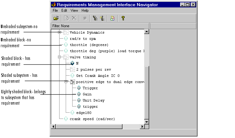
The following example shows that nodes for the N block in the valve timing subsystem and the positive edge to dual edge conversion subsystem are shaded, indicating they have requirements associated with them. The nodes under the positive edge to dual edge conversion subsystem are lightly shaded, indicating they belong to a subsystem that has requirements associated with it.

Stateflow Chart with Requirements
| Note
Stateflow allows for multiple transitions at the same level to have the same name. However, the Requirements Management Interface does not support associating requirements documents with transition peers that have the same name.
|
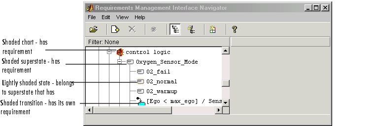
This example shows the control logic Stateflow chart (in the fuel rate controller subsystem of the fuelsys model) with requirements.

MATLAB M-File with Requirements
This example shows the M-file engine.m with requirements
.

 | Viewing Requirements in the Navigator | | Changing or Deleting a Requirement |  |


