| SimPowerSystems |
  |
Zigzag Phase-Shifting Transformer
Implement a zigzag phase-shifting transformer with a configurable secondary winding connection
Library
Elements
Description

The Zigzag Phase-Shifting Transformer block implements a three-phase transformer with a primary winding connected in a zigzag configuration and a configurable secondary winding. The model uses three single-phase, three- winding transformers. The primary winding connects the windings 1 and 2 of the single-phase transformers in a zigzag configuration. The secondary winding uses the windings 3 of the single phase transformers, and they can be connected in the following manner:
- Y
- Y with accessible neutral
- Grounded Y
- Delta (D11), delta leading Y by 30 degrees
- Delta (D1), delta lagging Y by 30 degrees
| Note
The D11 and D1 convention assumes that the Y voltage phase angle is at noon (12) on a clock display. D1 and D11 refer respectively to 11 AM (-30 degrees) and 1 PM (+30 degrees).
|
If the secondary winding is connected in Y, the secondary phase voltages are leading or lagging the primary voltages by the Phi phase angle in the parameters of the block. If the secondary winding is connected in Delta (D11), an additional phase shift of 30 degrees is added to the phase angle. If the secondary winding is connected in Delta (D1), a phase shift of -30 degrees is added to the phase angle.
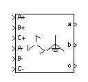
The block takes into account the connection type you have selected and the icon of the block is automatically updated. An output port labeled N is added to the block if you select the Y connection with accessible neutral for the secondary winding.
The saturation characteristic, when activated, is the same as the one described for the Saturable Transformer block.
Dialog Box and Parameters

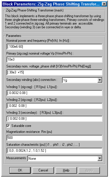
- Nominal power and frequency
- The nominal power rating, in volt amperes (VA), and nominal frequency, in hertz (Hz), of the transformer.
- Primary (zigzag) nominal voltage Vp
- The phase-to-phase nominal voltage in volts rms, for the primary winding of the transformer.
- Secondary nominal voltage and phase shift
- The phase-to-phase nominal voltage, in volts rms, and the phase shift, in degrees, for the secondary winding of the transformer.
- Secondary winding (abc) connection
- The phase connection for the secondary winding.
- Winding 1 (zigzag): [R1(p.u.) L1(p.u.)]
- The resistance and leakage inductance of the windings 1 of the single-phase transformers used to implement the primary winding of the Zigzag Phase-Shifting Transformer.
- Winding 2 (zigzag): [R2(p.u.) L2(p.u.)]
- The resistance and leakage inductance of the windings 2 of the single-phase transformers used to implement the primary winding of the Zigzag Phase-Shifting Transformer.
- Winding 3 (secondary): [R1(p.u.) L1(p.u.)]
- The resistance and leakage inductance of the windings 3 of the single-phase transformers used to implement the secondary winding of the Zigzag Phase-Shifting Transformer.
- Saturable core
- If selected, implements a saturable core.
- Magnetization resistance Rm
- The magnetization resistance Rm, in p.u, when the saturation is simulated. This parameter is visible only if the Saturable core parameter is selected.
- Magnetizing branch: [Rm(p.u.) Lm(p.u.)]
- The magnetization resistance Rm and inductance Lm, in p.u., when the saturation is not simulated. The Magnetizing branch parameter is not visible in the dialog box if the Saturable core parameter is selected.
- Saturation characteristic
- The saturation characteristic for the saturable core. Specify a series of current/ flux pairs (in p.u.) starting with the pair (0,0). This parameter is visible only if the Saturable core parameter is selected.
- Measurements
- Select Phase voltages to measure the voltage across the primary and secondary winding terminals of the block.
- Select Phase currents to measure the current flowing through the primary and secondary windings of the block.
- Select Fluxes and magnetization currents to measure the flux linkage, in volt seconds (V.s), and the magnetization current (when the saturation is simulated).
- Select All measurement (V, I, Flux) to measure the winding voltages, currents, magnetization currents, and the fluxes.
- Place a Multimeter block in your model to display the selected measurements during the simulation. In the Available Measurement list box of the Multimeter block, the measurements are identified by a label followed by the block name.
- If the Secondary winding (abc) connection parameter is set to Y, Yn, or Yg, the labels are as follows.
Measurement
|
Label
|
Phase voltages
|
Uan:, Ubn:, Ucn:
or:
Uag:, Ubg:, Ucg:
|
Phase currents
|
Ian:, Ibn:, Icn:
or:
Iag:, Ibg:, Icg:
|
Fluxes
|
Flux_a:, Flux_b:, Flux_c:
|
Magnetization currents
|
Imag_a:, Imag_b:, Imag_c:
|
- If the Secondary winding (abc) connection parameter is set to Delta (D11) or Delta (D1), the labels are as follows.
Measurement
|
Label
|
Phase voltages
|
Uab:, Ubc:, Uca:
|
Phase currents
|
Iab:, Ibc:, Ica:
|
Fluxes
|
Flux_a:, Flux_b:, Flux_c:
|
Magnetization currents
|
Imag_a:, Imag_b:, Imag_c:
|
- The labels of the primary zigzag winding are as follows.
Measurement
|
Label
|
Phase voltages
|
UA:, UB:, UC:
|
Phase currents
|
IA:, IB:, IC:
|
Example
See the help text of the psb48pulsegtoconverter demo.
See Also
Three-Phase Transformer (Three Windings)
 | Voltage Measurement | | Power System Command Reference |  |


