
| SimPowerSystems |   |
Building the Electrical Circuit with powerlib Library
The graphical user interface makes use of the Simulink functionality to interconnect various electrical components. The electrical components are grouped in a special library called powerlib.
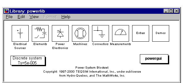
Open the Power System Blockset library by entering the following command at the MATLAB prompt:
This command displays a Simulink window showing icons of different block libraries. 
You can open these libraries to produce the windows containing the blocks to be copied into your circuit. Each component is represented by a special icon having one or several inputs and outputs corresponding to the different terminals of the component:
circuit1.
Vs.
Z_eq.
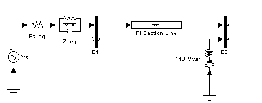
Rs_eq of the circuit can be obtained from the Parallel RLC Branch block. Duplicate the Parallel RLC Branch block, which is already in your circuit1 window, set the R parameter according to Figure 1-1, and set the L and C parameters respectively to infinity (inf) and zero (0).
inf.
Rs_eq.
outputs, and name it B1. Also copy the Ground block (select the block with an output connection).
Resize the various components and interconnect blocks by dragging lines from outputs to inputs of appropriate blocks.
In order to complete the circuit of Figure 1-1, you need to add a transmission line and a shunt reactor. You will add the circuit breaker later in Session 3.
The model of a line with uniformly distributed R, L, and C parameters normally consists of a delay equal to the wave propagation time along the line. This model cannot be simulated as a linear system because a delay corresponds to an infinite number of states. However, a good approximation of the line with a finite number of states can be obtained by cascading several PI circuits, each representing a small section of the line.
A PI section consists of a series R-L branch and two shunt C branches. The model accuracy depends on the number of PI sections used for the model. Copy the PI Section Line block from the Elements library into the circuit1 window, set its parameters as shown in Figure 1-1, and specify one line section.
The shunt reactor is modeled by a resistor in series with an inductor. You could use a Series RLC Branch block to model the shunt reactor. Set the R and L values corresponding to the active and reactive power specified in Figure 1-1 (Q=110 Mvar; P=110/300=0.37 MW at V=424.4 kV rms and f= 60 Hz).
You might find it more convenient to use a Series RLC Load block that allows you to specify directly the active and reactive powers absorbed by the shunt reactor.
Copy the Series RLC Load block, which can be found in the Elements library of powerlib. Name this block 110 Mvar. Set its parameters as follows:
Note that, as no reactive capacitive power has been specified, the capacitor disappears on the block icon when the dialog box is closed.
Add a receiving end bus bar B2 by duplicating B1, and interconnect all these new blocks as shown.
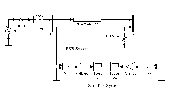
You need a Voltage Measurement block to measure the voltage at bus bar B1. This block can be found in the Measurements library of powerlib. Copy it and name it U1. Connect its positive input to the second output of bus bar B1 and its negative input to a new Ground block.
In order to observe the voltage at the bus bar B1 measured by the Voltage Measurement block named U1, a display system is needed. This could be any device found in the Sinks library of Simulink.
Open the Sinks library of Simulink and copy the Scope block in your circuit1 window. If the scope were connected directly at the output of the voltage measurement, it would display the voltage in volts. However, electrical engineers in power systems are used to working with normalized quantities (per unit system). The voltage is normalized by dividing the value in volts by a base voltage corresponding to the peak value of the system nominal voltage. In this case the scaling factor K is
Copy a Gain block from the Simulink library and set its gain as above. Connect its output to the Scope block and connect the output of the Voltage Measurement block to the Gain block. Duplicate this voltage measurement system at the bus bar B2, as shown below.

 | Session 1: Simulating a Simple Circuit | Interfacing the Electrical Circuit with Simulink |  |