

| SimPowerSystems |   |
Implement a synchronized pulse generator to fire the thyristors of a six-pulse converter
Library
Description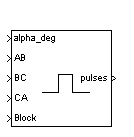
The Synchronized 6-Pulse Generator block can be used to fire the six thyristors of a six-pulse converter. The output of the block is a vector of six pulses individually synchronized on a three-phase commutation voltage. The pulses are generated alpha degrees after the increasing zero crossings of the commutation voltages.
The figures below display the synchronization of the six pulses for an alpha angle of 0 degrees. The pulses are generated exactly at the zero crossings of the synchronization voltages.
The Synchronized 6-Pulse Generator block can be configured to work in double-pulsing mode. In this mode two pulses are sent to each thyristor: a first pulse when the alpha angle is reached, then a second pulse 60 degrees later, when the next thyristor is fired.
The figures below display the synchronization of the six pulses for an alpha angle of 30 degrees and with double-pulsing mode. Notice that the pulses are generated 30 degrees after the zero crossings.
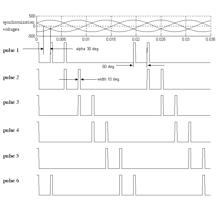
The pulse ordering at the output of the block corresponds to the natural order of commutation of a three-phase thyristor bridge. When you connect the Synchronized 6-Pulse Generator block to the pulses input of the Universal Bridge block (with the thyristors as the power electronic device), the pulses are sent to the thyristors in the following order:
When you build your own three-phase thyristor bridge with single thyristor blocks, you need to connect the pulse signals of the Synchronized 6-Pulse Generator block to the gate inputs of the corresponding thyristors.
Dialog Box and Parameters
Inputs and Outputs
Example
The psbsixpulses.mdl demo uses a synchronized 6-Pulse Generator block to fire the thyristors of a six-pulse thyristor bridge. The bridge is fed by a three-phase voltage source and it is connected to a resistive load. 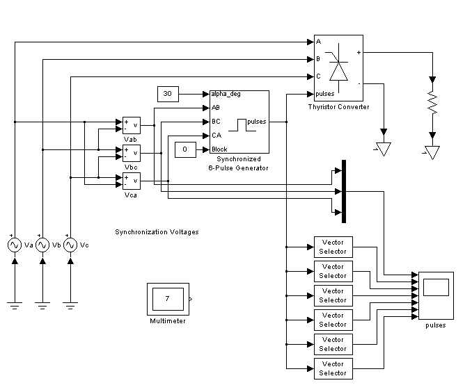
A first simulation is performed with an alpha angle of 0 degrees. Open the Constant block connected at input 1 of the Synchronized 6-Pulse Generator block and set its value to 0. Start the simulation. The voltages of the six thyristors are displayed in the next figure. The resulting DC voltage at the output of the rectifier is also displayed.
The thyristor voltages for alpha = 0 degrees are: 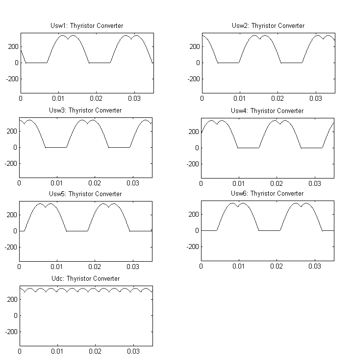
Now change the value of the alpha angle to 30 degrees and start the simulation. Notice that the waveforms of the thyristor voltages look different from the previous case. The thyristors begin to conduct with a lag of 30 degrees and the resulting DC voltage at the output of the rectifier has changed.
The thyristor voltages for alpha = 0 degrees are: 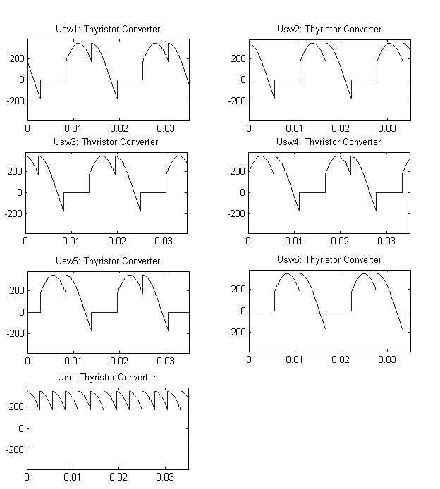
The figures show that the rms value of the DC voltage can be controlled by the alpha angle applied to the Synchronized 6-Pulse Generator block.
 | Surge Arrester | Synchronized 12-Pulse Generator |  |