| SimMechanics |
  |
Configuring the Body Blocks
Setting the Body properties is similar for each bar, but with different
- Mass properties
- Lengths and orientations
- Center of gravity (CG) positions
- Body coordinate systems (CSs)
to be entered into the dialog boxes.
In contrast to the first tutorial, where you specify Body CS properties with respect to the absolute World CS, in this tutorial, you specify Body CS origins on the bars in relative coordinates, displacing Bar1's CS1 relative to Ground_1, Bar2's CS1 relative to Bar1, and so on, around the machine loop. You can refer the definition of a Body CS to three types of coordinate systems:
- To World
- To the other Body CSs on the same Body
- To the Adjoining CS (the coordinate system on a neighboring body or ground directly connected by a Joint to the selected Body CS).
The components of the displacement vectors for each Body CS origin continue to be oriented with respect to the World axes. The rotation of each Body's CG CS axes is also with respect to the World axes, in the Euler X-Y-Z convention.
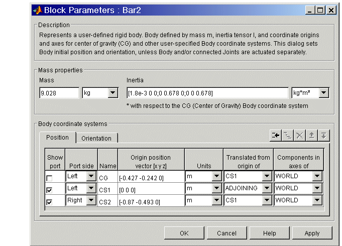
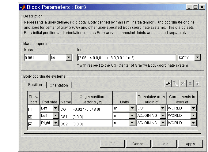
The following three tables summarize the body properties for the three bars.
Bar1 Mass and Body CS Data (MKS Units)
Property
|
Value
|
Variable Name
|
Mass
|
5.357
|
m_1
|
Inertia tensor
|
[1.07e-3 0 0; 0 0.143 0;
0 0 0.143]
|
inertia_1
|
CG Origin
|
[0.03 0.282 0] from CS1
|
cg_1
|
CS1 Origin
|
[0 0 0] from ADJOINING
|
cs1_1
|
CS2 Origin
|
[0.063 0.597 0] from CS1
|
cs2_1
|
CG Orientation
|
[0 0 83.1] from WORLD
|
orientcg_1
|
Bar2 Mass and Body CS Data (MKS Units)
Property
|
Value
|
Variable Name
|
Mass
|
9.028
|
m_2
|
Inertia tensor
|
[1.8e-3 0 0; 0 0.678 0;
0 0 0.678]
|
inertia_2
|
CG Origin
|
[-0.427 0.242 0] from CS1
|
cg_2
|
CS1 Origin
|
[0 0 0] from ADJOINING
|
cs1_2
|
CS2 Origin
|
[-0.87 0.493 0] from CS1
|
cs2_2
|
CG Orientation
|
[0 0 29.5] from WORLD
|
orientcg_2
|
Bar3 Mass and Body CS Data (MKS Units)
Property
|
Value
|
Variable Name
|
Mass
|
0.991
|
m_3
|
Inertia tensor
|
[2.06e-4 0 0; 0 1.1e-3 0;
0 0 1.1e-3]
|
inertia_3
|
CG Origin
|
[-0.027 -0.048 0] from CS1
|
cg_3
|
CS1 Origin
|
[0 0 0] from ADJOINING
|
cs1_3
|
CS2 Origin
|
[0 0 0] from ADJOINING
|
cs2_3
|
CG Orientation
|
[0 0 60] from WORLD
|
orientcg_3
|
Configuring the Bodies
Here are the common steps for configuring the Body dialogs of all three bars. See the three preceding tables for Body dialog box mass property (mass and inertia tensor) entries. The units are MKS: lengths in meters (m), masses in kilograms (kg), and inertia tensors in kilogram-meters2 (kg-m2).
- Open all three Body dialogs for each bar. Enter the mass properties for each from the tables in the Mass and Inertia tensor fields.
- Now work in the Body coordinate systems area, the Position pane:
- Set the Components in axes of menu, for each Body CS on each bar, to
WORLD.
- Leave units as default
m (meters).
- Set the Body CS properties for each Body CS on each bar from the data of the preceding tables:
- Enter the Body CS origin position data for CG, CS1, and CS2 on each bar
from the tables or from the corresponding MAT-file variables.
- Set the Translated from origin of menu entries for each Body CS on
each bar according to the "from" information in the tables.
- Select the Orientation pane by clicking its tab:
- Enter the Orientation vector for the CG on each bar from the tables or
from the corresponding MAT-files variables.
- Choose
WORLD for Relative to coordinate system in each case.
- Leave the other fields in their default values.


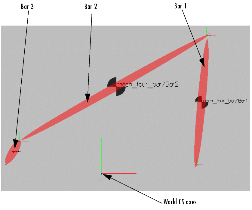
The front view of the four bar mechanism, rendered as equivalent ellipsoids in the virtual reality scene, looks like this.

 | Configuring the Ground and Joint Blocks | | Sensing Motion and Running the Model |  |


