

| Nonlinear Control Design Blockset | |
Nonlinear Control Design Blockset Startup
The Simulink system ncdtut2 contains a block diagram representation of the experiment described above. You can open the system by typing ncdtut2 at the MATLAB prompt.
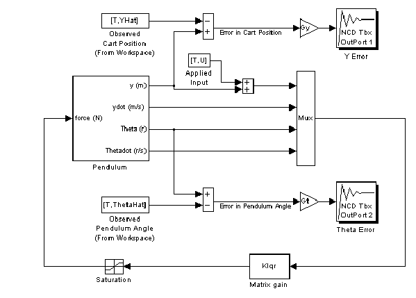 Notice that in addition to the inherent nonlinearities of the system equations, limits on the voltage applied to the motor result in an actuation saturation constraint of one Newton. Notice that the system contains two NCD blocks as we use both pendulum angle and cart position signals to perform identification. The basic approach to performing system identification using the Nonlinear Control Design Blockset involves constraining the error signals. To form error signals, use the From Workspace block to import observed data into your system and then subtract the simulated signal.
Before continuing, you must define some system parameters and load the observed data. At the MATLAB command line, type
penddata% Loads T, U, yHat, ThetaHat, g, and Mcl = 0.61/2; % Distance to center of mass of pendulum (m)% i.e., one-half length of pendulumm = 0.21; % Mass of pendulum (kg)
In the real world system, sensors measure only cart position and pendulum angle and we calculate the velocities using finite difference estimators. Here we ignore such considerations and assume full state feedback. Also in the real world, the measured and input signals contain noise. Here we simply generated the observed output signals (yHat and ThetaHat) by simulating the system at the solution point (m=0.3 and l=0.32). We did not add noise.
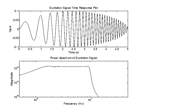
We apply a modified chirp signal, U, to the system. We find such signals useful in system ID applications because they contain contributions from a specified frequency range [1]. The signal U possesses (nearly) uniform frequency components between 1Hz and 10Hz. A time response plot and power spectral analysis of the signal appear below.
We use gain blocks to magnify and normalize the error signals before passing them to the NCD block. Note that the position error is magnified Gy = 200 times, whereas the angle error is magnified by a factor Gt = 100. Alternatively, you could have weighted the signals using the Constraint Editor dialog box as described in the "Edit Menu" section of Reference. We suggest the convention of using gain blocks to normalize signals (i.e., weighting all constraint segments of an output) and constraint segment weighting for weighting one constraint segment of the same output relative to another.
| | A System Identification Problem | Adjusting Constraints | |