
| Embedded Target for Motorola MPC555 |   |
Output driver for MIOS 16-bit Parallel Port I/O Submodule (MPIOSM)
Library
Embedded Target for Motorola MPC555
Description
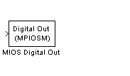
The MIOS Digital Out block sets the state of selected pins (bits) on the MIOS 16-bit Parallel Port I/O Submodule (MPIOSM) of the MPC555. The Bits field specifies a vector of numbers in the range 0..15, corresponding to pins MPIO32B0..MPIO32B15 on the MPIOSM.
The input to the block is a wide vector with one signal element per pin. When the input signal is greater than zero, a logical 1 is written to the corresponding pin. When the input signal is less than or equal to zero, a logical zero is written to the corresponding pin.
If you want to write to several digital output pins at the same sample rate, using a single MIOS Digital Out block with a vector input signal will result in more efficient code. However, if you want to update different output pins at different sample rates, you must use a separate MIOS Digital Out block for each rate.
Refer to section 15.13, "MIOS 16-bit Parallel Port I/O Sub module (MPIOSM)," in the MPC555 Users Manual for further information.
Dialog Box
0..15. Each number corresponds to a pin (MPIO32B0..MPIO32B15) on the MPIOSM. | MIOS Digital In | MIOS Digital Out (MPWMSM) |  |