| Fuzzy Logic Toolbox | |
ANFIS from the Command Line
As you can see, generating an FIS using the ANFIS Editor GUI is quite simple. However, as you saw in the last example, you need to be cautious about implementing the checking data validation feature of anfis. You must check that the checking data error does what is supposed to. Otherwise you need to retrain the FIS.
In this section we describe how to carry out the command line features of anfis on a chaotic times-series prediction example.
Using anfis for Chaotic Time-Series Prediction
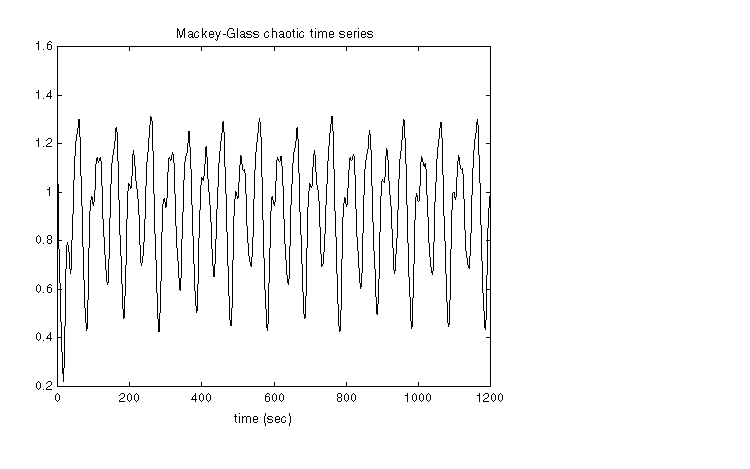
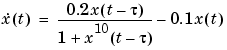
The demo mgtsdemo uses anfis to predict a time series that is generated by the following Mackey-Glass (MG) time-delay differential equation.
This time series is chaotic, and so there is no clearly defined period. The series will not converge or diverge, and the trajectory is highly sensitive to initial conditions. This is a benchmark problem in the neural network and fuzzy modeling research communities.
To obtain the time series value at integer points, we applied the fourth-order Runge-Kutta method to find the numerical solution to the above MG equation; the result was saved in the file mgdata.dat. Here we assume x(0) = 1.2,  = 17, and x(t) = 0 for t < 0. To plot the MG time series, type
In time-series prediction, we want to use known values of the time series up to the point in time, say, t, to predict the value at some point in the future, say, t+P. The standard method for this type of prediction is to create a mapping from D sample data points, sampled every  units in time, (x(t-(D-1)),..., x(t-), x(t)), to a predicted future value x(t+P). Following the conventional settings for predicting the MG time series, we set D = 4 and = P = 6. For each t, the input training data for
 anfis is a four-dimensional vector of the following form.
The output training data corresponds to the trajectory prediction.
For each t, ranging in values from 118 to 1117, the training input/output data will be a structure whose first component is the four-dimensional input w, and whose second component is the output s. There will be 1000 input/output data values. We use the first 500 data values for the anfis training (these become the training data set), while the others are used as checking data for validating the identified fuzzy model. This results in two 500-point data structures: trnData and chkData.
Here is the code that generates this data.
for t=118:1117,
Data(t-117,:)=[x(t-18) x(t-12) x(t-6) x(t) x(t+6)];
end
trnData=Data(1:500, :);
chkData=Data(501:end, :);
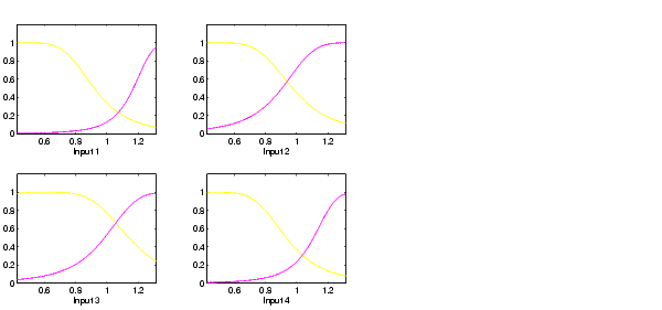
To start the training, we need an FIS structure that specifies the structure and initial parameters of the FIS for learning. This is the task of genfis1.
Since we did not specify numbers and types of membership functions used in the FIS, default values are assumed. These defaults provide two generalized bell membership functions on each of the four inputs, eight altogether. The generated FIS structure contains 16 fuzzy rules with 104 parameters. In order to achieve good generalization capability, it is important to have the number of training data points be several times larger than the number parameters being estimated. In this case, the ratio between data and parameters is about five (500/104).
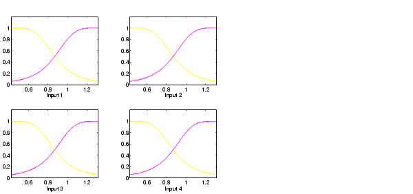
The function genfis1 generates initial membership functions that are equally spaced and cover the whole input space. You can plot the input membership functions using the following commands.
subplot(2,2,1)
plotmf(fismat, 'input', 1)
subplot(2,2,2)
plotmf(fismat, 'input', 2)
subplot(2,2,3)
plotmf(fismat, 'input', 3)
subplot(2,2,4)
plotmf(fismat, 'input', 4)
These initial membership functions are shown below.
This takes about 4 minutes on a Sun SPARCstation 2 for 10 epochs of training. Because the checking data option of anfis was invoked, the final FIS you choose would ordinarily be the one associated with the minimum checking error. This is stored in fismat2. The following code will plot these new membership functions.
subplot(2,2,1)
plotmf(fismat2, 'input', 1)
subplot(2,2,2)
plotmf(fismat2, 'input', 2)
subplot(2,2,3)
plotmf(fismat2, 'input', 3)
subplot(2,2,4)
plotmf(fismat2, 'input', 4)
To plot the error signals, type
Here error1 and error2 are the root mean squared error for the training and checking data, respectively.
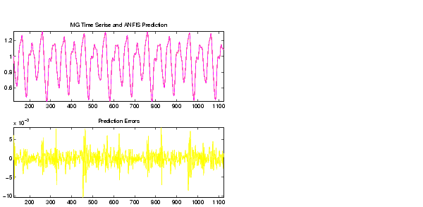
In addition to these error plots, you may want to plot the FIS output versus the training or checking data. To compare the original MG time series and the fuzzy prediction side by side, try
anfis_output = evalfis([trnData; chkData], fismat2);
index = 125:1124;
subplot(211), plot(t(index), [x(index) anfis_output]);
subplot(212), plot(t(index), x(index) - anfis_output);
Note that the difference between the original MG time series and the anfis estimated values is very small. This is why you can only see one curve in the first plot. The prediction error is shown in the second plot with a much finer scale. Note that we have only trained for 10 epochs. Better performance is expected if we apply more extensive training.
| | ANFIS Editor GUI Example 2: Checking Data Doesn't Validate Model | More on ANFIS and the ANFIS Editor GUI | |