| DSP Blockset |
  |
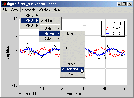
Step 7 -- Set the Vector Scope Display Colors. The Vector Scope's display can show the three signals (noisy sine wave, filtered noisy sine wave, and original sine wave) using different colors and line styles. It can also show a channel legend:
- Show the channel legend by clicking the Axes menu and selecting Channel legend.
- See the options for setting the color, style, and marker of each channel by clicking the Channels menu in the Vector Scope's display. If you connected your blocks as in Figure , Model Using the Digital Filter Design Block to Implement Filters,, the channels in the Vector Scope display (listed in the Channels menu) correspond to the following signals:
-
Channel 1 -- Noisy sine wave
Channel 2 -- Filtered noisy sine wave
Channel 3 -- Original sine wave
- Rerun the simulation and compare the original sine wave, noisy sine wave, and filtered noisy sine wave in the Vector Scope display. You can see that the lowpass filter filters out the high-frequency noise in the noisy sine wave.
| | Step 6 -- Set Simulation Parameters and Run the Model | | Multirate Filters | |